

.svg)
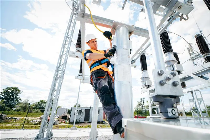
Often hidden beneath power substations, industrial facilities, and large electrical installations, grounding grids play a vital role in protecting equipment, infrastructure, and – most importantly – human life.
A grounding grid is a network of interconnected conductors, typically made of copper or galvanized steel, buried in the earth to provide a low-resistance path for electrical currents to safely dissipate into the ground. These grids are designed to handle fault currents, lightning strikes, and other transient over voltages by directing them away from equipment and personnel.
Grounding grids form the foundation of an effective grounding – also known as earthing – system, which is essential for maintaining voltage stability and ensuring the safe operation of electrical equipment. They are most commonly found in:
- Electrical substations
- Power generation plants
- Industrial facilities
- Data centers
- Telecommunications hubs
- Wind and solar farms
- Hospitals
Why Grounding Is Necessary
Grounding serves several critical purposes:
Personnel Safety
In the event of a fault – a failure in the electrical system caused by incidents such as outages or lightning strikes – grounding ensures that dangerous voltages do not persist on exposed conductive parts. This minimizes the risk of electric shock.
Equipment Protection
Sensitive electrical and electronic equipment can be damaged by transient voltages. A grounding grid helps divert these surges safely into the earth.
System Stability
Grounding provides a reference point for system voltages, which is essential for the proper operation of protective relays and circuit breakers.
Lightning Protection
Grounding grids help dissipate the high-energy currents from lightning strikes, reducing the risk of fire or equipment failure.
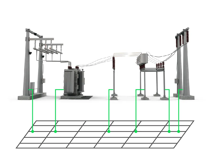
Components of a Grounding Grid
A typical grounding grid consists of the following elements:
- Horizontal Conductors: These are laid out in a grid pattern (e.g., square or rectangular) and buried at a shallow depth, usually one to two feet below the surface
- Vertical Ground Rods: Driven deeper into the earth to improve the overall grounding resistance, especially in areas with high soil resistivity
- Grounding Electrodes: These may include rods, plates, or rings that enhance the contact area with the soil
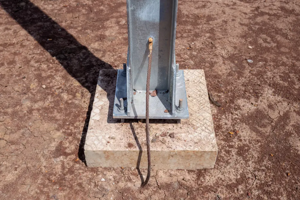
- Connections to Equipment: All metallic parts of electrical equipment, enclosures, and structures are bonded to the grid
The design of the grid is influenced by factors such as soil resistivity, fault current magnitude, and the physical layout of the facility.
How Grounding Grids Work
When a fault occurs – say, a lightning strike hits a transmission line, or a transformer develops an internal short – the resulting surge of electrical energy must be safely dissipated. The grounding grid provides a low-impedance path for this current to flow into the earth.
Here’s how the process works:
- Current Injection: The fault current enters the grounding grid through the connected equipment or structure.
- Current Distribution: The grid distributes the current across its network of conductors, minimizing localized heating and voltage rise.
- Dissipation into Earth: The current flows from the grid into the surrounding soil, where it is absorbed and neutralized.
The effectiveness of this process depends on the resistance to ground, which is influenced by soil type, moisture content, temperature, and the geometry of the grid.
Key Design Considerations
Designing a grounding grid is a complex engineering task that must balance safety, performance, and cost. Key considerations include:
Soil Resistivity
Soil resistivity is a measure of how easily electrical current can pass through the ground. It varies with soil composition, moisture, and temperature. Engineers often conduct a soil resistivity survey using the Wenner or Schlumberger method to inform the grid design.
Grid Geometry
The layout of the grid – spacing between conductors, depth of burial, and number of ground rods – affects its resistance and current distribution. A denser grid with more conductors generally offers better performance.
Touch and Step Voltage
These are critical safety parameters:
- Touch Voltage: The potential difference between a grounded object and the feet of a person touching it
- Step Voltage: The voltage difference between two points on the ground a step apart
The grid must be designed to keep these voltages within safe limits during fault conditions.
Corrosion Resistance
Materials used in grounding grids must withstand corrosion over time. Copper is preferred for its conductivity and durability, but galvanized steel is often used for cost reasons.
Testing and Maintenance
Even the best-designed grounding grid can degrade over time due to corrosion, soil movement, or construction activities. Regular testing is essential to ensure continued performance. Common tests include:
- Fall-of-Potential Test: Measures the resistance between the grid and remote earth
- Clamp-on Ground Resistance Test: A non-intrusive method for measuring resistance in multi-grounded systems
- Soil Resistivity Testing: Periodically reassessing soil conditions to detect changes that may affect grounding performance
Maintenance may involve replacing corroded conductors, improving soil conductivity (e.g., with bentonite or conductive concrete), or expanding the grid.
How GPRS Helps Protect Grounding Grids During Excavation
Grounding grids are an indispensable element of power infrastructure, providing a vital layer of protection against electrical hazards. By accurately locating and mapping these systems before excavating or trenching near them, we can mitigate risks, protect personnel and equipment, and ensure the continued reliability and resilience of our electrical networks.
GPRS offers 99.8%+ accurate utility locating services designed to mitigate the risk of subsurface damage by providing you with the information you need to break ground safely. Using ground penetrating radar (GPR) scanners and electromagnetic (EM) locating, our SIM-certified Project Managers create comprehensive infrastructure maps to keep you on time, on budget, and safe.
What can we help you visualize? Click below to schedule a service or request a quote today!
Frequently Asked Questions
What does GPRS give me when I hire them to conduct a utility locate?
Our Project Managers flag and paint our findings directly on the surface. This method of communication is the most accurate form of marking when excavation is expected to commence within a few days of service.
GPRS also uses Real-Time Kinematic (RTK) Positioning to collect data points of findings. We use this data to generate a plan, KMZ file, satellite overlay, or CAD file to permanently preserve results for future use.
GPRS does not provide land surveying services. If you need land surveying services, please contact a professional land surveyor.
Please contact us to discuss the pricing and marking options your project may require.
Can GPR scanning locate PVC piping and other non-conductive utilities?
GPR scanning is exceptionally effective at locating all types of subsurface materials. There are times when PVC pipes do not provide an adequate signal to ground penetrating radar equipment and can’t be properly located by traditional methods. This is why GPRS Project Managers are expertly trained at multiple methods of utility locating, including utilizing electromagnetic (EM) locating, to complement GPR scanning.