3D Laser Scanning Services in Arizona

As an architecture, engineering, or construction professional, you understand that projects require a tremendous amount of planning and coordination. GPRS 3D Laser Scanning can deliver accurate as-builts, point clouds, 2D CAD drawings, 3D photogrammetry, and 3D BIM models to expedite project planning and reduce change orders, delays, and costs.

Whether you are a general contractor or facility manager planning renovations or modifications, or an architect or engineer who requires precise project data, GPRS provides accurate existing conditions documentation, reality capture, and scan-to-BIM services to bring your design and construction projects in on time, and on budget.

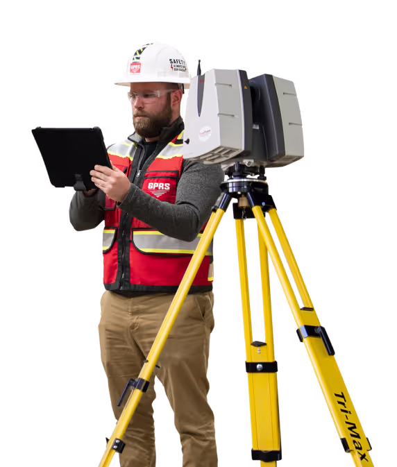
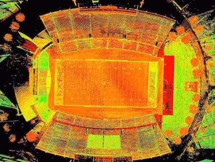
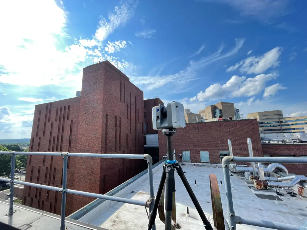
When you need accurate architectural, structural, and MEP system dimensions, locations, and layouts for design, prefabrication, clash detection, facility modifications, or asset management, call GPRS. 3D laser scanning minimizes shutdowns and disruptions, eliminates the need for site revisits, and provides accurate as-built data to reduce risk and increase project efficiency.
A man in a hard hat holding a tablet.

Phoenix 3D Laser Scanning

480-244-1787laser@gprsinc.com

GPRS Project Managers

GPRS is the leading provider of 3D laser scanning services in Arizona. Our Project Managers document your site with the Leica ScanStation P-Series and the Leica RTC360 3D laser scanners, capturing up to 2 million data points per second with 2-4 millimeters accuracy. Each Project Manager completes the most extensive training program in the industry, with 80 hours of hands-on classroom training and 320 hours of mentorship in the field, plus another 40 hours of LiDAR training to deliver expertise in 3D laser scanning equipment and field knowledge.

A 3D image of a factory with pipes and valves.A drawing of a road with a red line on it.A 3D drawing of a building with a staircase.

GPRS Mapping & Modeling Team

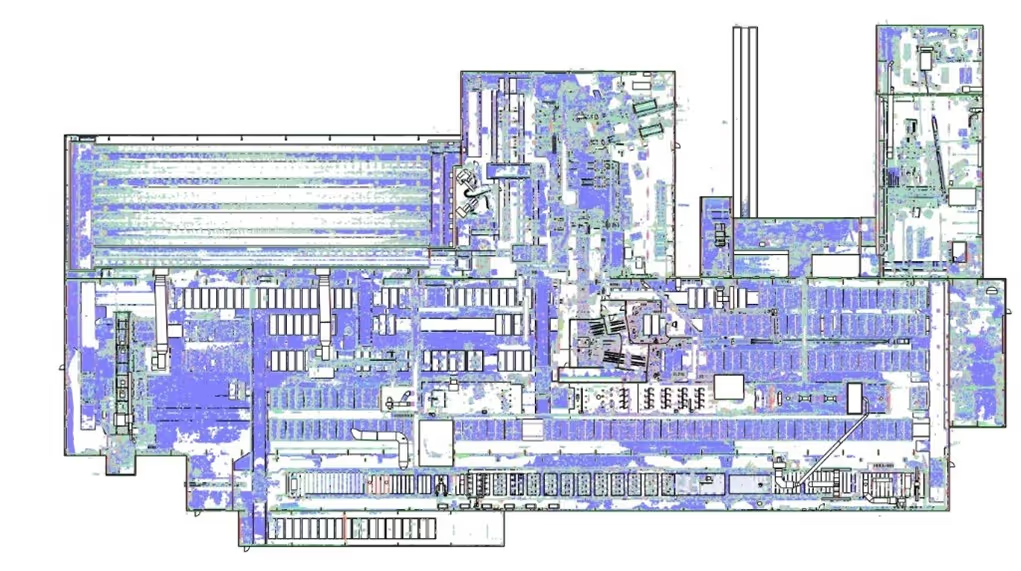
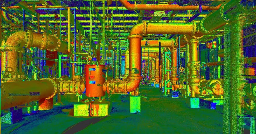
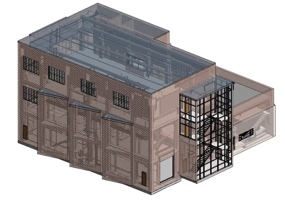
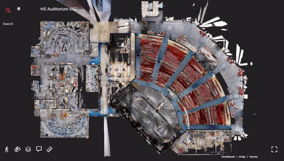
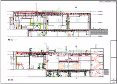
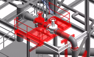
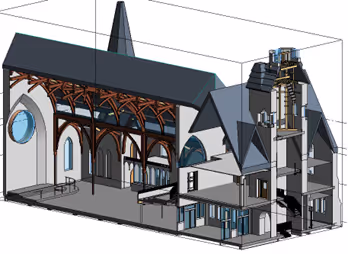
Construction drawings and models streamline planning, visualization, and coordination on your project because they provide a single source of truth for designers, architects, engineers, and contractors. GPRS’ in-house Mapping & Modeling Team can customize as-built data, 2D CAD drawings, 3D BIM models, 3D mesh models, virtual tours via WalkThru 3D, digital twins, floor plans via FLRPLN, and more to ensure you have all the information you need to get the job done right, delivered via GPRS’ SiteMap® digital storage software and app.

Maps and models can be produced at any level of detail in a variety of formats such as Revit, AutoCAD, ReCap, Navisworks, Civil 3D, BIM360, A360, Bentley, Leica Cyclone, Cintoo, and more. We have optimized workflows for importing data, registration, creating deliverables, quality checks, and transferring data to clients.

Not sure what you need? Not a problem. Our experienced Project Managers will work closely with you to define the project scope and use the right equipment and software to accurately map and model your project to accomplish your goals.

WHY CHOOSE US? 

THE GPRS DIFFERENCE.

With GPRS, clients can rest assured that our rigorously trained Project Managers use state-of-the-art technology to deliver the accurate as built information you need to do the job right. GPRS leads the industry to deliver precise as built information to enhance communication and collaboration among your project teams.

GPRS 3D Laser Scanning Services can bring these benefits to your project:

  • Collect up to two million data points per second with the highest-quality survey-grade laser scanners
  • Capture exact dimensions and measurements of your project site
  • Expedite planning and design with accurate as-builts
  • Eliminate site disruption and revisits
  • Receive precise point clouds, 2D drawings, and 3D models to improve collaboration and coordination
  • Tour the location, add digital notes, and even measure with a virtual tour
  • Reduce project risks, change orders, delays, accidents, and costs
GPRS main Logo: Intelligently Visualizing the built world | GPRS

GPRS 3D Laser Scanning Services in Arizona

A blue and white drawing of a building with a lot of wires.
As-Built Services
As-built services capture exact architectural, structural, and MEP system dimensions and layout of existing buildings, facilities, and sites, making them invaluable for design, construction, renovations, and modifications.
Learn More
A green and blue image of a factory with pipes and valves.
Point Clouds
3D laser scanners record highly accurate digital measurements of sites and assets in the form of a point cloud and can be used to create 2D CAD drawings and 3D BIM models that improve project workflows, shorten turnaround times, and reduce costs.
Learn More
A 3D model of a building with a staircase.
3D BIM Modeling
Intelligent 3D Building Information Models (BIM) provide contractors, engineers, architects, and facility managers an accurate digital twin of buildings and infrastructure to collaborate on design, construction, and operations.
Learn More
A picture of a building with a red circle in the middle.
3D Photogrammetry
3D rendered images can be used to create virtual tours, floorplans, topographic maps, point clouds, 3D models, and more for planning, analysis, and calculations.
Learn More
A drawing of a building with a red roof and a green roof.
2D CAD Drawings
GPRS can translate 3D laser scan data into 2D CAD drawings that provide your team with up-to-date floor plans, elevations, sections, details, isometric drawings, reflected ceiling plans, and more.
Learn More
A red pipe with a blue wire running through it.
Clash Detection
3D laser scanning captures as-built site conditions with 2-4 mm accuracy, helping to identify potential clashes, prefabricate components, and plan a flawless installation.
Learn More
A 3D drawing of a church with a steeple.
Design-Build
3D laser scanning provides accurate as-built site data to prevent expensive rework by identifying any mistakes early in the design through the construction phase.
Learn More
A stadium seating chart with a red line on the field.
Drone Imagery
GPRS offers rectified photogrammetry, aerial video and images, LiDAR scans, 2D orthomosaic images, CAD drawings, 3D models, and 3D fly throughs thanks to a wide-range of drone services operated by FAA Licensed pilots.
Learn More

We provide 3D Laser Scanning Services to these Arizona counties & many more:

  • Maricopa County
  • Pima County
  • Pinal County
  • Yavapai County
  • Mohave County
  • Yuma County
  • Coconino County
  • Cochise County
  • Navajo County
  • Apache County

Our portfolio of work includes projects in these Arizona cities & many more:

  • Phoenix, AZ
  • Tucson, AZ
  • Mesa, AZ
  • Chandler, AZ
  • Scottsdale, AZ
  • Gilbert, AZ
  • Glendale, AZ
  • Tempe, AZ
  • Peoria, AZ
  • Surprise, AZ

3D Laser Scanning a Grain Facility

With the millions of data points collected, GPRS’ Mapping & Modeling team could create an accurate LOD 200 Revit 2021 BIM model of this processing facility.
GPRS mobilized to Fairmont, Nebraska to 3D laser scan a food grade corn processing facility. The target objects of point cloud data acquisition were tanks, silos, hoppers, conveyors, support cables, machinery, equipment, cleaning house and loading drive-thru. GPRS’ engineering team created an LOD 200 Revit model of the facility. The client also requested floor flatness analysis/contour mapping around several tanks.
Meta Title: 3D Laser Scanning a Grain Facility Meta Description: GPRS mobilized to Fairmont, Nebraska to 3D laser scan a food grade corn processing facility. Header: A GPRS Case Study: 3D Laser Scanning a Grain Facility Images: Link: https://www.gp-radar.com/services/mapping-modeling Alt Tag: Point cloud of tank farm at grain facility. Caption: Point cloud of tank farm at grain facility. Link: https://www.gp-radar.com/services/mapping-modeling Alt Tag: Point cloud close-up view of catwalks on tanks. Caption: Point cloud close-up view of catwalks on tanks. Link: https://www.gp-radar.com/services/mapping-modeling Alt Tag: Point cloud plan view of facility. Caption: Point cloud plan view of facility. Link:https://www.gp-radar.com/services/mapping-modeling Alt Tag: Modeled linework plan view of facility. Caption: Modeled linework plan view of facility. Link: https://www.gp-radar.com/services/mapping-modeling Alt Tag: 3D Revit model of catwalk area. Caption: 3D Revit model of catwalk area. Link: https://www.gp-radar.com/services/mapping-modeling Alt Tag: Point cloud close-up of catwalk. Caption: Point cloud close-up of catwalk. Link: https://www.gp-radar.com/services/mapping-modeling Alt Tag: Close-up of discharge area under grain hopper tank. Caption: Close-up of discharge area under grain hopper tank. Link: https://www.gp-radar.com/services/mapping-modeling Alt Tag: Point cloud isometric view of food corn processing facility. Caption: Point cloud isometric view of food corn processing facility. Link: https://www.gp-radar.com/services/mapping-modeling Alt Tag: Point cloud of food corn processing facility. Caption: Point cloud of food corn processing facility. Link: https://www.gp-radar.com/services/mapping-modeling Alt Tag: 3D Revit model of spout and conveyor areas. Caption: 3D Revit model of spout and conveyor areas. Link: https://www.gp-radar.com/services/mapping-modeling Alt Tag: LOD 200 Revit 3D model of facility in elevation view. Caption: LOD 200 Revit 3D model of facility in elevation view. Link: https://www.gp-radar.com/services/mapping-modeling Alt Tag: 3D Revit model of facility. Caption: 3D Revit model of facility. Link: https://www.gp-radar.com/services/mapping-modeling Alt Tag: Tank farm contour mapping plan PDF of tanks. Caption: Tank farm contour mapping plan of northern tanks. Link: https://www.gp-radar.com/services/mapping-modeling Alt Tag: Tank farm contour mapping plan PDF of tanks. Caption: Tank farm contour mapping plan of southern tanks. Location: Fairmont, NE Task: GPRS mobilized to Fairmont, Nebraska to 3D laser scan a food grade corn processing facility. The target objects of point cloud data acquisition were tanks, silos, hoppers, conveyors, support cables, machinery, equipment, cleaning house and loading drive-thru. GPRS’ engineering team created an LOD 200 Revit model of the facility. The client also requested floor flatness analysis/contour mapping around several tanks. Challenge: The client needed accurate and precise detail of the facility in point cloud and model form, especially the congested areas. The client was concerned with differences in tank displacement; therefore, they requested tank farm slab elevation contours. Solution: An experienced project manager captured more than 160 scan locations with a Leica survey-grade laser scanner. The facility was scanned from the ground to capture the tanks, bins, silos, hoppers and discharge area under the 11 hoppers. The facility was 3D laser scanned at elevations with stair and elevator access to capture the spouting and conveyors at the top of each tank, silo and bin. Scanning was completed from the accessible roof to capture the equipment, cables and machinery present. The cleaning house was also scanned at multiple elevations to capture the entire room. The project manager increased the resolution and density of the point cloud to capture more detail in congested areas with small conduits, piping and flanges. With the millions of data points collected, GPRS’ engineering team could model this project with accuracy and precision. Concrete slab flatness can be quickly analyzed with laser scanning. GPRS engineers colored the cloud in respect to elevation to illustrate high or low points in the concrete. Deliverables: GPRS delivered unified point clouds in PTS file format, structured individual scans in E57 file format, a colorized point cloud (.rcs and/or .rcp file format) and JetStream Viewer files to the client. An LOD 200 Revit 2021 BIM model was created with the following elements: • Basic structural elements including exposed columns and beams • The general shape of 6 tanks with high detail at discharge locations and high detail on gates to conveyors • Rail spur within vicinity of tanks • Catwalks and equipment on tanks • Fall protection • Edge of adjacent building • Approximate grade GPRS delivered a graphical elevation map, contours and spot elevations for the requested tanks. This included AutoCAD, PDF, and Civil 3D files to generate contours around the tank farm. Added Value: GPRS works closely with each client to ensure their needs are met. Point cloud files were immediately uploaded to Cintoo for the client’s use. They were able to add annotations or tags to anything they might want modeled. To minimize modeling costs, all modeling is done as a “best fit” method, utilizing solids overlaid on the point cloud data. To verify the spot elevations, GPRS also provided tank roof elevations shown colored by point cloud elevation.
All
3D Laser Scanning
3D Laser Scanning
Mapping & Modeling

Brick Manufacturer Uses 3D Laser Scanning For Facility Upgrades

This client requested as-built data, 2D CAD drawings, and a 3D BIM model of their 150,000 square feet facility in 12 business days. The 3D model will allow this manufacturer to discover any discrepancies between the design model and existing conditions so they can make necessary adjustments before the facility upgrade begins.
The demand for wood molded brick continues to grow as architects and designers utilize more brick in building designs. To keep up with this demand, our client, the largest molded brick manufacturer in the United States, is planning upgrades to its Shoemakersville, Pennsylvania facility. These upgrades include adding a second kiln to increase capacity and modernizing equipment to improve product quality. The client requested point cloud data, 2D CAD drawings, and a 3D Revit model to understand the existing conditions of the facility.
The client requested point cloud data, 2D CAD drawings, and a 3D Revit model to understand the existing conditions of the facility.
Brick Manufacturer Uses 3D Laser Scanning For Facility Upgrades Location: Shoemakersville, Pennsylvania Task: The demand for wood molded brick continues to grow as architects and designers utilize more brick in building designs. To keep up with this demand, our client, the largest molded brick manufacturer in the United States, is planning upgrades to its Shoemakersville, Pennsylvania facility. These upgrades include adding a second kiln to increase capacity and modernizing equipment to improve product quality. The client requested point cloud data, 2D CAD drawings, and a 3D Revit model to understand the existing conditions of the facility. Challenge: Our client was on a tight timeline. They requested as-built data, 2D drawings and a 3D BIM model of their 150,000 square feet facility in 12 business days. To complete the facility upgrades, they needed line, equipment, and tie-in points. Solution: 150,000 sq. ft. of space was 3D laser scanned in two days on-site with the Leica P50 ScanStation and the RTC360 laser scanner. 279 laser scans were taken to capture complete as-built data of the site’s structure, equipment, and MEP. Deliverable: GPRS delivered an LOD 200 design-intent architectural, structural, and MEP Revit Model, 2D AutoCAD floor plans and interior elevations, and an RCS point cloud file. MEP piping and conduit 2 inch and larger, HVAC ductwork, pumps, motors and equipment were 3D modeled to within ¼ inch accuracy. The 3D model will allow our client to discover any discrepancies between the design and existing conditions so they can make necessary adjustments before the facility upgrade begins. Added Value: Coordinating the work of designers with structural, MEP, and other construction teams is often difficult. Laser scanning provides a fast and accurate way to collect large amounts of site measurement data which can be used to expedite the retrofit design process. 3D scanning will help this client design to the actual as-built conditions, reducing clashes and change orders. Inaccurate data would slow teams down, increase the risk of miscommunication, and create prefabrication and installation problems that could lead to rework.
All
3D Laser Scanning
3D Laser Scanning
Mapping & Modeling

Restoring Frank Lloyd Wright’s Unity Temple

Architects and mechanical contractors could plan both the demolition of the existing systems and the implementation of the new systems without jeopardizing the Frank Lloyd Wright Unity Temple's aesthetics and spatial design.
To laser scan both the interior and exterior of Frank Lloyd Wright’s Unity Temple and produce a 3D BIM model for historical renovation documentation.
GPRS laser scanned the interior and exterior of Frank Lloyd Wright’s Unity Temple to produce a 3D BIM model for historical renovation documentation.
Location: Unity Temple in Oak Park, Illinois Task: To laser scan both the interior and exterior of Frank Lloyd Wright’s Unity Temple and produce a 3D BIM model for historical renovation documentation. Challenge: The challenge in this case was to be able to thoroughly document the 1909 Frank Lloyd Wright masterpiece—in order to prepare for a multi-million dollar building restoration—without compromising the building’s historical identity or disrupting ongoing tourism and church activities within Unity Temple. Solutions: Building Information Modeling (BIM) has become a major practice within the AEC industry, specifically for new construction, adaptive reuse, or buildout projects. But how does this practice of “build twice” translate to restoring an early 19th century architectural marvel? By means of High Definition Surveying (HDS). HDS is a non-contact measuring tool that collects visible information of existing conditions in a fast, precise way while, at the same time, reducing damage risks and time associated with traditional measuring methods. Visible information is captured in 360 degrees, generating a 3D point cloud with accuracy up to 2 to 4mm. These point clouds ultimately become 3D virtual worlds of the building, making the method a fast and cost effective way to generate as-built documentation (both 2D and 3D) for project analysis and coordination. In the case of Unity Temple, TruePoint was hired for its expertise in historical preservation by means of laser scanning and BIM modeling. TruePoint’s team of architects and engineers performed a comprehensive laser scan of the building’s interior (temple, offices, mechanical basement, classrooms, etc.), exterior, roof, and skylights in order to capture explicit detail of Unity Temple’s current condition. TruePoint then created a 3D Revit model from the point cloud data so that the construction management firm and subcontractors (mechanical contractors, concrete restoration, architects, etc.) could investigate the building’s existing state and accurately assess their project designs for restoring Unity Temple. Deliverables: Deliverables included a 3D Revit model of the building’s interior, exterior, roof, and skylights; a colorized point cloud in Autodesk Recap file formats (.rcp/.rcs) to be used directly in Autodesk Software (Revit, AutoCAD, Navisworks, etc.); and TruView photographs. Added Value: The colorized point cloud generated from laser scanning gave explicit detailed information that would be otherwise nearly impossible or extremely difficult to document without risking damage to the fragile building elements. Examples of two key architectural features are the intricate window panes (e.g., clerestories, skylights) and the wood trim throughout Unity Temple. Both of these features were collected in the point cloud data in congruence with other building information (structure, mechanical systems, etc.). Additionally, TruePoint trained the client on how to create 2D elevations, sections, and a Reflected Ceiling Plan (RCP) directly from the point cloud data within AutoCAD. These AutoCAD sheets contained precise measurements and photographs, making it quick and easy for the client to identify the exact piece and location of each element for its removal, restoration, and re-implementation. TruePoint also provided the client with TruViews. The TruView utilizes a free plug-in for Internet Explorer in order to view each scan location from the scanner’s perspective. This offers a quick, easy way to take rudimentary measurements, make hyperlink notes, and perform project collaboration, thereby reducing the hassle, time, and cost associated with on-site visits. Another added bonus of producing a comprehensive point cloud and BIM model of Unity Temple was documenting the existing mechanical room and tunnel in relation to the entire structure. Mechanical contractors and architects could then plan both demolition of the existing systems and implementation of the new systems without jeopardizing Frank Lloyd Wright’s aesthetic and spatial design.
All
3D Laser Scanning
3D Laser Scanning
Mapping & Modeling

We Have Two Ways To Request An Online Quote:

  1. If you are familiar with Laser Scanning, fill out the form below
  2. If you are new to Laser Scanning, click here for more detailed prompts

GPRS
INTELLIGENTLY VISUALIZING THE BUILT WORLD®