

.svg)

Highlights
THE BOTTOM LINE
By 3D laser scanning the COG line area and producing an LOD 300 Revit model, GPRS gave the team precise as‑built data to plan the gas pipe relocation with fewer clashes, faster coordination, and reduced downtime.
Industry
Automotive
Service
3D Laser Scanning, Mapping & Modeling
Location
Middletown, Ohio
GPRS Project Manager Insight
GPRS can align point cloud data to existing survey control, site specific control, or existing models if coordinates are received prior to scanning and data processing.
Deliverables
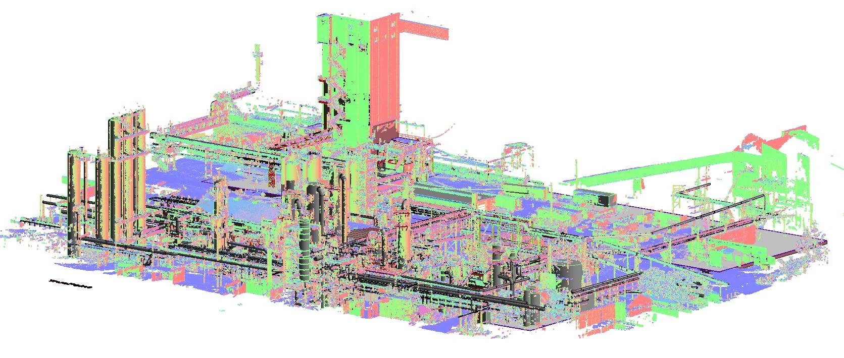
Intensity map point cloud (.rcs file), a JetStream Viewer file, and an LOD 300 Revit 3D model.
PROJECT APPLICATION
ASK
Task
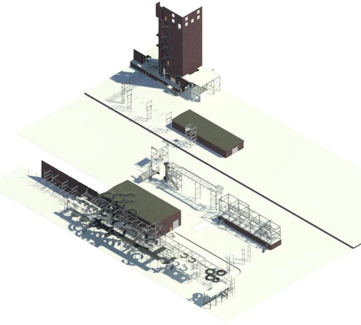
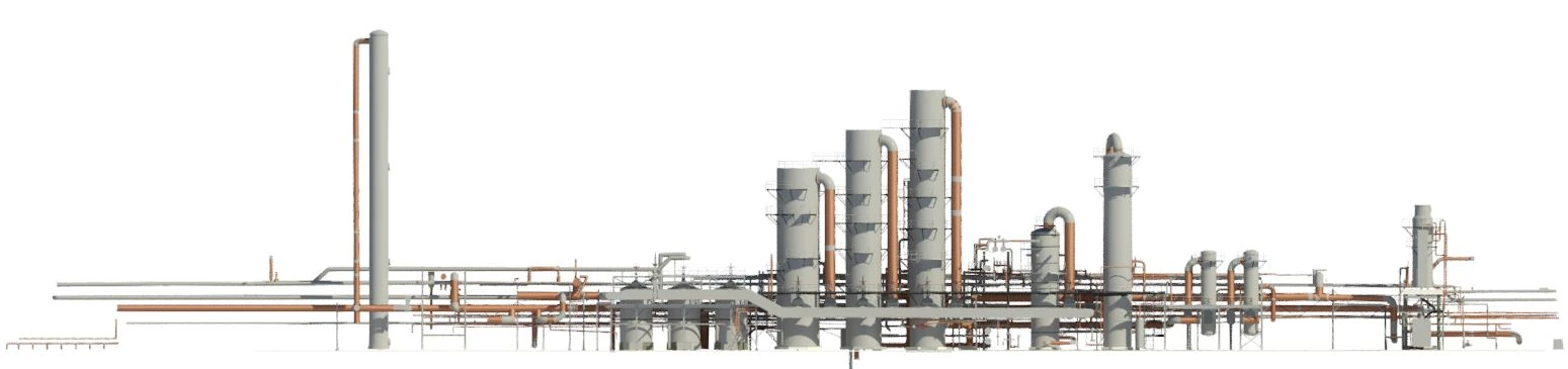
A leading producer of rolled-steel products for the automotive industry was relocating a pipe in the COG line and requested GPRS 3D Laser Scanning to capture as-built site details and create a LOD 300 Revit 3D model. The client needed 330,000 square feet of the facility to be laser scanned and modeled for this project.
PROBLEM
The client needed a full structural and MEP layout of the facility to support the relocation of a 12" diameter pipe. To complete this complex task, they required a highly detailed 3D model, along with a point cloud and model aligned to a previous GPRS mobilization performed in 2020.
GPRS captured the structure, piping, and equipment for the following areas:
- Pipe rack from the gas holder west to the tar precipitators
- Platform, walkway, and pipes on the north side of the tar precipitators
- Pipe rack from the gas holder to the coke battery
- Area on the east end of the coke battery and truck loadout area
- Aisleway under the coke bench
- Exhauster Building main floor on the east end
- Exhauster Building basement on the east end
- Booster gas platform
Solution
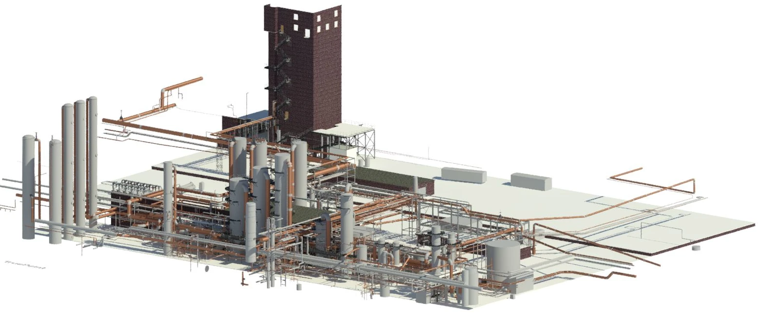
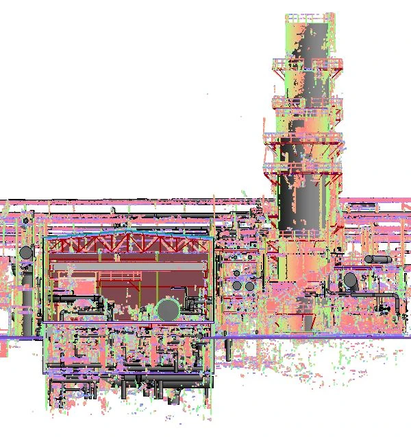
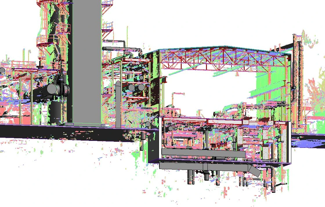
GPRS 3D laser scanned the plant with the Leica RTC360 and the Leica P50 ScanStation. In 184 laser scans, the Project Manager captured complete as-built data of the facility. The Mapping and Modeling team aligned the new scans and model to previous scans and model in the adjacent and overlapping areas.
Benefits
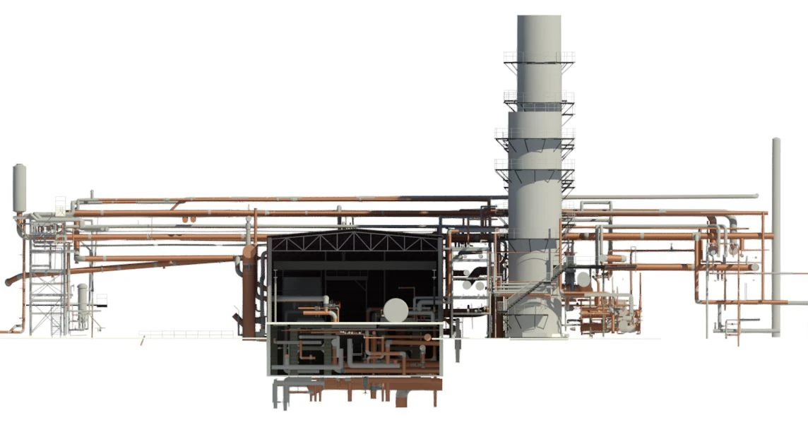
The field‑verified geometry and 3D BIM model gave the team precise as‑built data to plan the gas pipe relocation with fewer clashes, faster coordination, and reduced downtime.
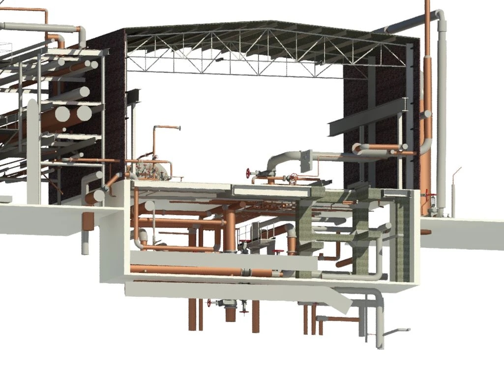
3D Modeling Scope of Work:
• Revit 2019 software, design-intent 3D model
• Two LOD 300 models were created: MEP & Architectural/Structural model
• MEP piping 2” in diameter and above
• Valves, fittings, and flanges
• MEP equipment
• Basic structural elements including exposed columns and beams
• Walkway dimensions only, low detail on railings
• Piping connections into the vessels
CASE STUDY GALLERY
.webp)
.avif)


.avif)