

.svg)
Vapor intrusion (VI) is a serious public health and environmental issue.
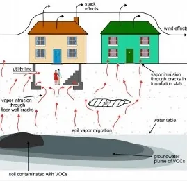
It occurs when volatile chemicals migrate from contaminated soil or groundwater into the indoor air of overlying buildings. This pathway is like radon gas infiltration but often involves hazardous industrial chemicals such as chlorinated solvents and petroleum hydrocarbons. Left unchecked, vapor intrusion can expose occupants to carcinogens and other toxic compounds, creating long-term health risks and complicating property transactions and redevelopment projects.
The Dangers of Vapor Intrusion
The main risk of vapor intrusion is long-term exposure to volatile organic compounds (VOCs). These include trichloroethylene (TCE), tetrachloroethylene (PCE), benzene, and vinyl chloride. These chemicals are connected to cancer, brain damage, liver and kidney harm, and developmental issues. Unlike acute exposure scenarios, vapor intrusion typically results in low-level but persistent exposure. This can be difficult to detect without specialized testing. Indoor sources such as cleaning products can make matters worse by masking contamination.
Vapor intrusion carries legal and financial implications as well as health risks. Regulatory agencies increasingly require vapor-intrusion assessments during property transactions, brownfield redevelopment, and site remediation. Failure to address VI can lead to liability under environmental laws, costly retrofits, and reputational damage for developers and property owners.
How to Conduct Vapor-Intrusion Assessments
A vapor-intrusion assessment starts with a conceptual site model (CSM). This model shows possible sources, pathways, and receptors. Sources typically include contaminated groundwater plumes, soil impacted by spills, or non-aqueous phase liquids (NAPLs). Vapors migrate through the vadose zone and enter buildings through cracks, utility penetrations, and other openings in the foundation.
The assessment process generally involves:
- Soil Gas Sampling: Take samples from under building slabs or near the source area to help measure VOC concentrations
- Indoor Air Sampling: Comparing indoor air concentrations to outdoor background levels to determine if subsurface contamination is contributing
- Sub-Slab Sampling: Installing vapor pins beneath the foundation to directly measure vapors before they enter the building
- Temporal Variability Analysis: Accounting for seasonal and pressure-driven changes that influence vapor migration
Advanced modeling tools are often used to predict indoor air concentrations based on subsurface data. These models incorporate site-specific parameters like soil permeability, building construction, and contaminant properties.
EPA Screening Tools and Attenuation Factors
The U.S. Environmental Protection Agency (EPA) offers tools to simplify vapor intrusion evaluations. The Vapor Intrusion Screening Level (VISL) Calculator is a cornerstone resource. It uses toxicity values, exposure assumptions, and attenuation factors to generate risk-based screening levels for groundwater, soil gas, and indoor air. Users enter site-specific concentrations. The tool then calculates if further investigation or mitigation is needed.
Attenuation factors (AFs) are critical in estimating indoor air concentrations from subsurface measurements. They show the ratio of indoor air concentration to subsurface concentration. This reflects how much dilution and resistance occur during vapor migration. EPA’s recommended default AFs are:
- Groundwater to Indoor Air: 0.001
- Sub-Slab Soil Gas to Indoor Air: 0.03
- Crawl Space Air to Indoor Air: 1.0
For example, if sub-slab soil gas contains 100 µg/m³ of benzene, applying the AF of 0.03 predicts an indoor air concentration of 3 µg/m³. These factors make screening easier, but they can change with site conditions. So, regulators usually ask for confirmatory sampling.
EPA also maintains a Vapor Intrusion Database that compiles attenuation factors from real-world sites, improving the accuracy of predictive models.
Mitigation Technologies
When assessments confirm unacceptable risk, mitigation becomes essential. The most common technology is sub-slab depressurization (SSD). It creates negative pressure under the foundation and vents vapors outside. SSD systems can be active, using fans, or passive, relying on natural pressure differentials. For crawl spaces, sub-membrane depressurization is common. It uses a sealed membrane over the soil. This membrane connects to a venting system.
Other approaches include:
- Building Pressurization: Adjusting HVAC systems to maintain positive indoor pressure, reducing vapor entry
- Sealing Entry Points: Applying vapor barriers and sealing cracks. This is rarely sufficient as a standalone measure
- Indoor Air Treatment: Using air-purifying units with activated carbon or photocatalytic oxidation for temporary mitigation
- Source Control: Excavating contaminated soil or implementing soil vapor extraction to eliminate the vapor source
Emerging technologies combine SSD with real-time monitoring and adaptive controls. This setup ensures steady performance, even when conditions change.
Cost Considerations
Mitigation costs vary widely based on building size, foundation type, and contamination severity. Passive systems are less expensive but may not achieve sufficient risk reduction. Indoor air treatment units provide a temporary fix but require regular maintenance and monitoring.
Long-term costs include operation, maintenance, and periodic verification sampling. Regulatory requirements often mandate annual inspections and performance checks, adding to lifecycle expenses. Developers should also factor in indirect costs such as project delays, stakeholder communication, and potential legal liabilities.
How GPRS Ensures the Safety & Success of Your Vapor-Intrusion Assessments
Vapor intrusion is a complex environmental issue. It demands careful assessment and smart solutions.
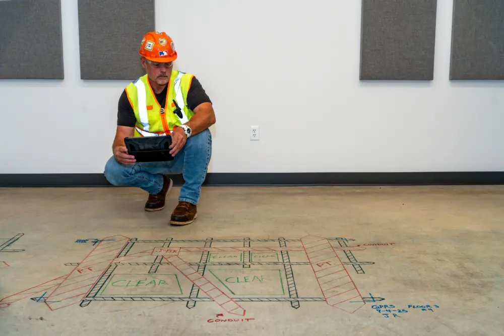
When you’re assessing the potential for VI concerns within a building by sampling sub-slab soil gas or vapor concentrations, it’s vital that you know what’s embedded within – and buried below – that concrete slab before you drill. Striking conduit, rebar or post tension cable could compromise the integrity of the structure, endanger the lives of you and your workers, and decimate your project’s schedule and budget.
GPRS provides precision concrete scanning & imaging services that tells you exactly where you can safely drill. You’ll be able to get your work done without causing any headaches for yourself or your clients.
Let us help keep you on time, on budget, and safe. Click below to schedule a service or request a quote today!
Frequently Asked Questions
How is ground penetrating radar used to identify tendons vs. rebar in a post-tensioned slab?
In post-tensioned structures, we typically find one mat of support rebar near the base of the slab. This mat is generally consistently spaced and remains at a constant elevation. Post-tension cables are generally found above this support mat and “draped” throughout the rest of the structure. The elevation of the cable is usually high near the beams and column lines and drapes lower through the span between beams and column lines. Knowledge of these structural differences allows us to accurately differentiate between components. Our Project Managers will leave you feeling confident in our findings and in your ability to drill or cut without issue.
How long does it take to scan an area for core drilling?
Ground penetrating radar (GPR) is an extremely efficient and rapid technology. Large areas can be easily and quickly scanned with the state-of-the-art GPR units utilized by GPRS Project Managers. Our standard layout for a typical core drilling location is 2’x2’. It usually takes about 10 minutes to scan and mark an area this size.
How accurate is GPR with marking anomalies in concrete?
When operated by our highly trained Project Managers, GPR’s typical accuracy is +/- ¼” to the center of the object in concrete we locate: conduit, post tension cables, and rebar. We can also pinpoint the depth of every object we locate in concrete with an accuracy of +/- 10-15%. Because our accuracy while scanning with GPR is so high, we can offer you our professional opinion to help you know where you are able to drill without the risk of hitting any objects marked on the slab. For safety concerns, we always tell our contractors to move one-to-two inches from any marked line as they prepare to cut or drill to be sure they safely miss any embedded objects. We are so confident in the accuracy of our Project Managers that we introduced the Green Box Guarantee, which states that when we place a Green Box within a layout prior to you anchoring or coring concrete, we guarantee that area will be free of obstructions. If we’re wrong, we will pay the material cost of the damage.
Can GPR scan concrete slab-on-grade?
Yes, it can. Unlike with X-ray, where both sides of a concrete slab must be accessible to obtain a picture of the subsurface structure, GPR only requires access to one side of a slab to obtain a comprehensive view of what’s inside the slab. This makes it an ideal technology for evaluating concrete slab-on-grade.