

.svg)
Post-tensioned (PT) slabs are essential in modern construction, especially high-rise construction, because they offer efficiency, durability, and the ability to span longer distances while reducing material usage.
Unlike precast slabs, PT slabs are cast-in-place, meaning the concrete is poured on-site, allowing flexibility in design and construction. Embedded within the slab are post-tensioning cables, made of high-strength steel tendons, which are positioned before the concrete pour and later tensioned. Once the concrete reaches adequate strength (2,500 – 3,000 psi), the cables are anchored and stressed, compressing the slab to enhance its structural integrity. Proper installation and anchoring of PT cables ensure minimal deflection, reduced cracking, and increased load-bearing capacity.
Installation and Sequence of Post-Tensioned Slab Creation
The installation of post-tensioned cables follows a precise sequence to ensure reliable performance. Before any concrete is poured, the post tension tendons are laid out in specific locations and/or patterns. The individual tendons are housed within ducts or sleeves to prevent direct contact with the concrete, to reduce friction during stressing.
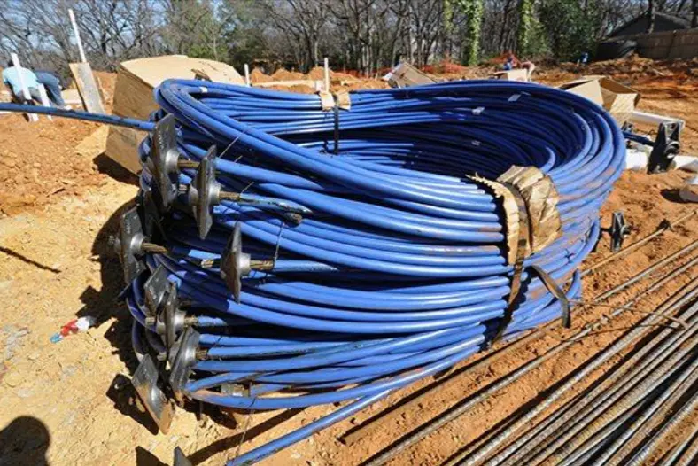
The cables are then anchored at their dead end, where they remain fixed, while the live end is left accessible for later tensioning. These are the “spaghetti ends” you can see emerging from the center of a newly poured PT slab to dangle over the side. The cable can be tensioned from either side, but the dead end generally arrives already seated in its anchor plate from the manufacturer, which will be grouted and capped after tensioning occurs.
Once the cables are in position – in either a uniform or banded layout – concrete is poured and allowed to cure. The generally required compressive strength for these tendons is 3,500 to 5,000 psi before stressing. Once the concrete has cured, the molds used to frame it are removed and hydraulic jacks are employed at each live end to stretch the tendon to its designed tension level, after which anchors secure the tendons permanently within the slab.
What is the Difference Between Dead End and Live End Anchoring?
Each PT cable features two anchor points:
- The dead end is embedded in the concrete before it is stressed. The dead ends of the tendons are secured by fixed anchor plates, locking them into position to prevent movement.
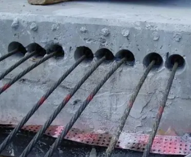
- The live end is where the “magic” happens because that’s where tensioning occurs. Each live end is exposed post-cure, so that the hydraulic jack can pull them to the necessary force before locking them in place. Once the tendons are secured, the stressing pocket is typically grouted or encased in concrete to protect the anchorage system.
Composition and Specifications of PT Cables & Anchors
Post tension cables are engineered to withstand significant tension forces while maintaining flexibility during installation. They are composed of high-strength steel tendons, ranging in diameter from 3/8" to 1/2", and are encased to reduce friction and shield them from corrosion.
Anchor wedges, plates, and encapsulations are integral components of the system, ensuring a secure attachment to the concrete structure. Grout is applied in bonded post-tensioning systems, to provide added durability and prevent destructive moisture intrusion, particularly in applications requiring long-term exposure to environmental elements.
Anchoring Mechanisms and Types of PT Anchors Explained
Anchoring post-tensioned cables requires specialized components to ensure stability and load distribution. At the dead end, fixed anchors secure tendons before tensioning begins, preventing unwanted movement within the slab. The live end allows controlled tensioning, where cables are individually stretched before locking them permanently.
There are several types of PT anchors and components used based on structural requirements.
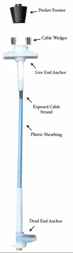
- Pocket formers are devices that form temporary recesses in the concrete to allow for stressing.
- Flat plate anchors are frequently used in thin slabs because they offer reliable load distribution while minimizing bulk.
- Multi-strand anchors accommodate multiple cables and are common in bridge decks and large-scale concrete structures, due to their need for high-capacity tensioning.
- Barrel anchors, which are compact in design, provide effective solutions for space-constrained applications while maintaining performance.
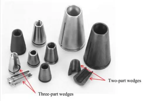
- Anchor/Cable Wedges are pieces of tapered, heat-treated, high-strength steel, whose serrations (teeth) penetrate the prestressing steel during the transfer of prestressing force. Anchorage systems sometimes contain two-part or three-part wedges.
Each anchoring method is selected based on load demands, slab thickness, and expected structural movement.
How Do You Reinforce PT Anchors?
Post-tensioned cable anchors experience high localized stresses, so they often require additional reinforcement to maintain stability.
- Bursting steel is incorporated around the live-end anchors to mitigate stress concentrations and prevent cracking or failure.
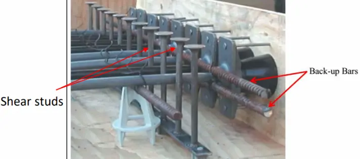
- Shear studs enhance anchorage integrity by increasing resistance against movement, especially in applications subjected to dynamic loads.
- Back-up bars assist in distributing the force across a broader surface area, reducing stress buildup and improving durability.
Together, these reinforcement strategies ensure the longevity and reliability of post-tensioned slab systems and reduce the risk of long-term degradation.
What Happens After the PT Slab is Tensioned?
When a PT cable is tensioned, it’s generally carrying about 80% of its tensile force. The average PT cable has a tensile strength of 270,000 pounds per square inch (psi). The stressing force for the average ½-inch 270 strand is used, which puts the stressing force at around 33,000 pounds. For comparison, rebar typically yields 60,000 psi.
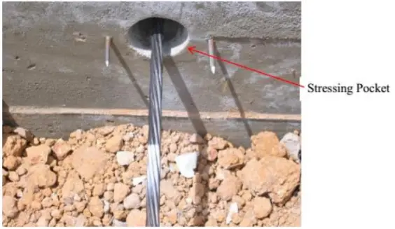
Once tension has been applied to the PT cable, its elongation is measured. A paint mark placed on the cable at end of the slab before it is tensioned allows you to measure the elongation post-tensioning. The area in which this takes place is called the cable’s stressing pocket: the recess created by the pocket that is formed between the stressing or intermediate anchorage and the edge of the concrete that allows nosepiece access for stressing. If you’re checking elongation on the dead end, it is then cut and the pocket grouted over.
Detecting Post-Tensioned Cables Using Ground Penetrating Radar
Ground penetrating radar (GPR) is an effective tool for identifying embedded PT cables within concrete slabs. Unlike the uniform grid-like patterns of rebar reinforcements, post-tensioned tendons display curved profiles, due to their specific placement and stressing process. Anchorage zones, particularly on live ends, generally produce stronger signal reflections. This allows construction engineers and GPRS Project Managers to differentiate between fixed-end anchors, stressing pockets, and the paths of the tendons.
GPR technology is frequently utilized as part of structural assessments, retrofits, and post-construction modifications to provide contractors accurate locations of all PT slab reinforcements, and to provide safe cutting, coring, and drilling clearances. The cables can also be placed in banded columns for additional reinforcement near pillars and elevator shafts, so it’s vital to know which kind of PT layout you’re dealing with prior to making any cuts into the slab.
The correct anchoring of post-tensioned cables is essential to achieving structural integrity and optimizing the performance of PT slabs. From installation and dead/live end anchoring to reinforcement measures and detection methods, each step in the process plays a critical role in ensuring reliability. Understanding the nuances of post-tensioning is crucial to maximizing efficiency while maintaining compliance with industry standards and keeping work teams safe.
GPRS Green Box Guarantee
GPRS is the only company in the U.S. that offers the Green Box Guarantee. Since 2017, our Project Managers have maintained a 99.8% accuracy rate in concrete scanning & imaging, so if we mark out a green box that says clear, we guarantee that you will not strike a PT cable or reinforcement. If you do, we’ll pay the material cost to repair it.
Frequently Asked Questions
How does GPR find post tension cables in concrete?
Ground penetrating radar (GPR) is used to locate post tension cables by emitting high-frequency radio waves into concrete and analyzing the reflected signals – that show up on a readout screen as hyperbolas – to identify embedded objects based on their dielectric properties and depth.
Learn more about how GPRS uses GPR.
What happens when a post tension cable is accidentally severed?
Severing a post tension cable can cause it to snap back violently due to the high tension, which poses serious safety risks and can compromise the structural integrity of the slab. The average cost to replace a severed post tension cable is between $20,000 and $30,000.
Learn more about GPRS concrete scanning and imaging services.