

.svg)
During structural engineering, engineers must place construction anchors in precise locations to ensure load-bearing integrity, comply with design specifications, and achieve long-term durability.
Precise anchor placement helps distribute structural loads to maintain the stability and safety of the building. Accurate positioning of anchors guarantees alignment with engineering plans, helping to avoid costly rework. And, correctly installed anchors reduce stress concentration and material fatigue, contributing to the structure’s resilience over time.
Clients often use 3D laser scanning at a jobsite to create 2D CAD drawings with precise dimensions and layouts. They can then plan, verify, and execute anchor installations with minimal errors.
This article will define a construction anchor and speak to the benefits of 3D laser scanning and CAD drawings for the engineering of construction anchors.
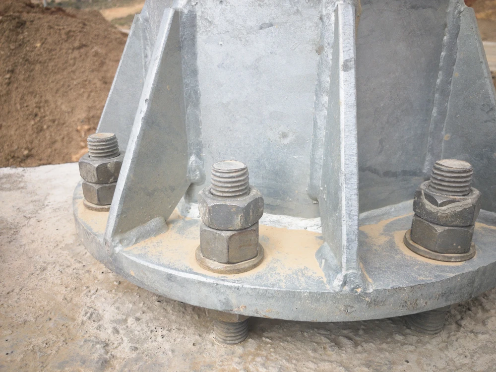
What is a Construction Anchor?
Construction anchors are used to attach structural components such as steel beams, mechanical systems, or façade elements to concrete or masonry. They come in various types, including expansion anchors, epoxy anchors, and cast-in-place anchors. Each type requires specific placement, depth, and spacing to meet engineering standards and manufacturer guidelines.
Improper anchor placement can lead to structural failures, misalignment of components, and costly rework. Accurate site data and documentation are crucial before drilling or embedding anchors.
What is the Role of Laser Scanning in the Engineering of Construction Anchors?
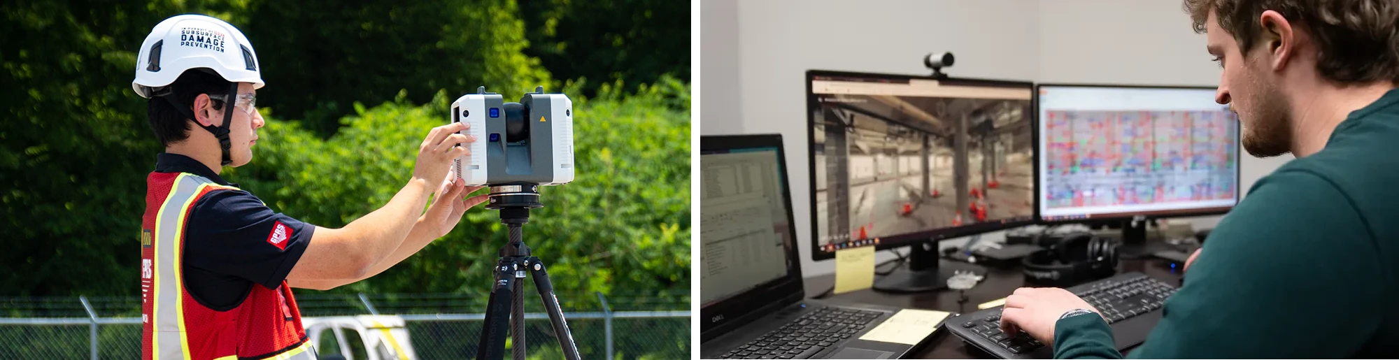
3D laser scanners use LiDAR (Light Detection and Ranging) technology to map millions of data points across a project site. They digitally capture every detail of a site, including the structural, architectural, and MEP features, plus underground utilities and concrete reinforcements, at incredible speeds with unparalleled accuracy. The technology delivers an overall site plan in 3D with exact building dimensions, locations, and layout for the engineering of construction anchors.
What are the Benefits of Laser Scanning for Anchor Placement?
Capture Accurate As-Built Conditions
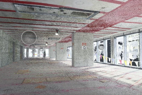
Laser scanning creates a precise 3D digital record of the site. This helps engineers confidently locate architectural, structural, and MEP elements. They can easily find walls, floors, columns, beams, and mechanical, electrical, and plumbing systems. This eliminates guesswork and ensures that anchors are placed in structurally sound areas.
Identify Subsurface Utility Locations
Scans show where flagged and painted markings are for buried utilities. This includes electrical, gas, water, sewer, steam, irrigation, and telecommunication lines, helping teams avoid costly hits and delays.
Reveal Hidden Concrete Elements
Laser scanning captures hidden concrete elements like rebar, conduit, and HVAC systems. This helps engineers avoid drilling into critical areas and maintain safety compliance.
Verify Site Dimensions with Precision
Laser scanning allows engineers to compare actual site conditions against design drawings. If there are differences between the planned and actual site conditions, adjustments can be made before installing the anchors.
Enable Remote Collaboration Across Teams
Point cloud data and TruViews can be shared digitally, allowing engineers, contractors, and project managers to review the site virtually, annotate areas of interest, and approve anchor layouts without being physically present.
Minimize Site Visits and Save Time
A single scan captures all necessary measurements, reducing the need for repeat visits. Engineers can extract all necessary measurements from the scan, saving time and reducing labor costs.
What is the Process for Scan to CAD?
The process of using laser scanning and CAD drawings for anchor engineering usually includes these steps:
- 3D Laser Scanning: A technician performs a 3D laser scan of the project area. The scan captures all visible surface and structural elements.
- Point Cloud Processing: The raw scan data is cleaned, aligned, and registered to create a unified point cloud. This step ensures accuracy and usability.
- CAD Modeling: Engineers extract relevant geometry from the point cloud and convert it into 2D CAD drawings.
- Anchor Engineering: Anchor locations are planned based on structural requirements and site conditions.
- Review and Approval: Structural engineers and project managers review the drawings. Adjustments are made as needed to accommodate field realities.
- Installation and Verification: Anchors are installed according to the CAD layout. Post-installation scans may be performed to verify placement and document the final condition.
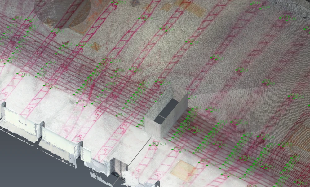
How are Point Clouds Converted to 2D CAD Drawings?
Point clouds are imported into CAD software to create customized 2D CAD drawings. CAD technicians use the raw laser scan data, or point cloud, to trace and model existing conditions with precision. The result is a customized 2D CAD drawing that reflects the actual site layout.
Once the engineer receives the CAD drawing, they can add the following information for installing construction anchors:
Anchor Placement Details
- Exact location of each anchor point (X and Y coordinates)
- Reference to structural elements (e.g., beams, columns, walls)
- Spacing and alignment relative to other anchors or features
Dimensions and Layout
- Overall dimensions of the area or component
- Distances between anchors
- Elevation views, if needed, to show vertical placement
Annotations and Notes
- Installation instructions or callouts
- Material specifications (e.g., anchor type, size, embedment depth)
- Tolerance requirements for placement accuracy
Structural Context
- Load-bearing elements and their relationship to anchor points
- Wall or slab thickness
- Reinforcement details (if anchors interact with rebar or mesh)
Compliance and Standards
- Reference to design codes or standards
- Approval stamps or revision history
Why Would an Engineer Use 2D CAD Drawings?
Anchor Layout Planning
Engineers use 2D CAD drawings to plan anchor locations with respect to structural grids, load paths, and architectural constraints. These drawings serve as the basis for drilling templates and installation.
Integration with Structural Plans
CAD drawings can be overlaid with structural and architectural plans to ensure anchor placement aligns with design intent. This is especially important in trade coordination where anchors must avoid clashes with other systems.
Permit and Compliance Documentation
Many jurisdictions require detailed drawings for permit approval. CAD drawings created from laser scans provide accurate documentation that meets regulatory standards.
Field Installation Support
Installers rely on 2D drawings for precise measurements and layout. These drawings can be printed, marked up, and used directly on-site to guide anchor drilling and placement.
Quality Assurance and Record Keeping
CAD drawings serve as a permanent record of anchor locations. This is useful for future inspections, renovations, or forensic analysis in case of structural issues.
What are Some Applications for Construction Anchors?
Below are some key applications for the placement of construction anchors:
Retrofit Projects
In older buildings, original drawings may be missing or inaccurate. Scanning provides a reliable foundation for anchor planning.
High-Rise Construction
Anchors for curtain walls, mechanical systems, and structural steel must be placed with extreme precision. Laser scanning ensures alignment across floors and elevations.
Industrial Facilities
In plants and refineries, anchors support heavy equipment and piping. Scanning helps avoid conflicts with existing infrastructure.
Healthcare and Lab Environments
Anchors for specialized equipment must meet strict tolerances. Scanning ensures compliance with both structural and operational requirements.
Case Study: Skanska Hired GPRS to Perform Concrete Scanning at an Aircraft Assembly Plant
Skanska partnered with GPRS to scan 1,100 sq. ft. of concrete in an airplane assembly plant using ground penetrating radar to identify rebar patterns and slab thickness before anchoring new wing stands to the lid and floor of the building.
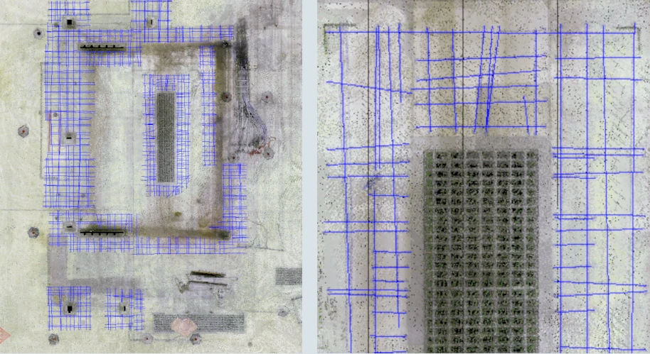
3D laser scanning captured the findings, which were converted into 2D CAD drawings, mapping rebar layers, base plates, embedded items, and proposed anchor locations with exact dimensions.
The result? A safer, smarter installation with zero surprises.
Read the case study: Skanska Hired GPRS for Concrete Scanning at an Aircraft Assembly Plant
Why Partner with GPRS for Laser Scanning and CAD for the Engineering of Construction Anchors?
GPRS is the only company in the U.S. that offers utility locating, concrete scanning, and reality capture services to digitally document your entire site, above and below ground. We deliver accurate as-builts, utility maps, 2D CAD drawings, 3D photogrammetry, and BIM models that integrate architectural, structural, and subsurface existing conditions.
Every GPRS Project Manager has completed the industry-leading Subsurface Investigation Methodology (SIM) certification. This rigorous program sets protocols for utility locating, concrete scanning, and 3D laser scanning that far exceed industry standards. It includes 80 hours of hands-on classroom training, 320 hours of field mentorship, and an additional 40 hours of LiDAR instruction to ensure expertise in scanning equipment and field applications.
Our 3D laser scanning and 2D CAD services transform how engineers approach anchor placement, providing field-verified data and actionable documentation to reduce risk, improve efficiency, and enhance collaboration.
How can GPRS support your next anchor engineering project with laser scanning and CAD?
Frequently Asked Questions
How Long Does 3D Laser Scanning Take?
GPRS has Project Managers across the country, allowing us to respond quickly with detailed quotes. Most jobs can be scanned in just a few hours, while larger sites may take a few days. Scanning entire facilities or campuses can take weeks. Yet, most projects are completed in hours or days.
How is 3D Laser Scan Data Registered?
The registration process is a collaborative effort. Registering a 3D laser scan point cloud involves aligning multiple scans of the same area taken from different positions into a single, coherent point cloud. This typically involves using specialized software like Autodesk Recap to import the data and align the scans. The Mapping & Modeling Team uses the software to spot overlapping areas in different scans. It captures the same physical features from slightly different angles. This helps the software identify corresponding points. Unwanted “noise” can be cleaned or deleted from the point cloud. Autodesk Recap software can remove unwanted data or noise. This includes reflections, moving objects, and background clutter. As a result, it creates a clean point cloud that shows the target project area. Proper registration ensures 3D laser scan measurements are accurate. This data can be exported for use in CAD or BIM software like Revit or AutoCAD.
How is 3D Laser Scan Data Processed?
At GPRS, once a site is scanned, we process the raw point cloud data by combining individual scans. We remove unwanted noise and convert the data into usable formats like 2D drawings or 3D models. The level of detail depends on the project’s needs, ranging from basic visuals to complex models. GPRS follows a structured workflow focused on accuracy, teamwork, and planning. We ensure efficient project execution. Our deliverables are high quality and tailored to each client's needs.