

.svg)
Subsurface utility mapping and concrete scanning both utilize ground penetrating radar (GPR) to locate and map subsurface utility lines and underground features, and to find post tension cables, rebar, and conduit in concrete.
When using GPR technology, accurately interpreting signal variations, identifying hyperbolas, and defining subsurface features is as much an art as it is a science. GPR requires significant training and hands-on experience, over several months or years, to accurately collect, interpret, and validate subsurface data.
So, it comes as no surprise that the industry continues to seek better ways to visualize subsurface conditions and simplify interpretation.
That’s where the quest for “true 3D” GPR comes from: the desire to create a technology that anyone can use with little to no training, yet provide accurate, real-time subsurface information in an immediately useable format.
However, if you do a quick Google search for 3D GPR, it is apparent that there is a good deal of confusion surrounding the term within the construction industry. The goal of this article is to clearly define GPR, 3D GPR, and High-Speed 3D GPR Array and its uses, and to make a fair, side-by-side comparison.
Ground penetrating radar is inherently a 3D technology, the data collected always represents subsurface conditions in three dimensions. The distinction lies not in the data itself, but in how it is captured, processed, and visualized. In most standard applications, GPR technicians interpret this data as 2D cross-sectional slices displayed on their screens. The growing interest in what is commonly referred to as “3D GPR” reflects a desire to move beyond these individual slices and visualize the data as a fully integrated 3D model. In reality, the third dimension has always been present; advanced processing techniques simply make it easier to see, interpret, and utilize that information in a more comprehensive way.
What is the Difference Between GPR, 3D GPR, and High-Speed 3D GPR Array?
GPR
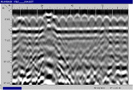
GPR collects data along a single line, producing a vertical cross-sectional profile, often called a radargram or B-scan, that shows depth versus distance. This method is ideal for utility locating and identifying objects embedded in concrete, providing a clear and efficient technology to visualize subsurface conditions.
3D GPR
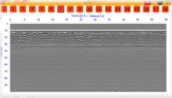
3D GPR captures data across a grid, combining multiple scan lines into a 3D data cube. This allows for horizontal “slice” views, known as C-scans, that provide top-down imagery. It uses a large number of antenna channels (e.g., 18 or more) to cover a wide path in one sweep, unlike single-channel GPR that requires numerous parallel lines. This method provides more detailed visualization and context but requires additional time, cost, and post-processing.
High Speed 3D GPR Array
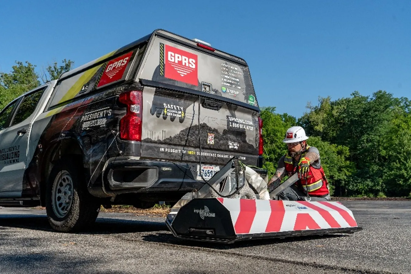
High-speed 3D GPR arrays collect data by using multiple radar antennas to scan large areas simultaneously, capturing dense 3D subsurface data in continuous motion. Mounted on vehicles, high-speed GPR arrays record data at high speeds and tight intervals, allowing rapid, high-resolution mapping without stopping between scan lines.
The Basics of GPR
What does GPR stand for?
GPR is the acronym for ground penetrating radar, also known as Georadar, ground penetration radar, or ground probing radar.
What is Ground Penetrating Radar?
Ground penetrating radar (GPR) is a non-destructive detection and imaging method that identifies elements that are either buried in the subsurface (utilities) or encased in concrete (PT cables, rebar, conduit, etc.).
According to the New York State Museum, GPR was invented in the 1930s as a tool for measuring the thickness of glaciers. The technology advanced to a stage where it became more affordable in the 1980s, but did not see widespread use in construction and other industries until the early 2000s.

How Does GPR Work?
GPR emits electromagnetic (EM) waves to the subsurface and calculates the time these waves need to travel through various subsurface materials and get back to the GPR receiver. When GPR bounces off a subsurface utility or a concrete feature, it creates a hyperbola on the receiver. By assessing the polarity (color), and depth of those hyperbolas, an experienced GPR technician can determine the type of material located.
What Does GPR Locate?
GPR can detect both metallic and non-metallic objects, which gives it a wide range of applications. It reveals all types of subsurface utilities, including electrical conduits, steam pipes, telecommunication lines, gas & oil lines, water lines, and sewer and storm pipes. GPR can also locate the presence of rebar, conduit, post tension cables, wire mesh, radiant heating tubes, and other structural elements hidden within concrete.
GPR can estimate concrete slab thickness by identifying the reflection from the bottom of the slab, even when only the top surface is accessible. This makes it a valuable tool for evaluating slab-on-grade and elevated systems such as pan deck encasements
It also enables accurate slab thickness measurement across large or complex areas, helping teams verify design assumptions, assess structural integrity, and reduce the risk of costly errors or damage.
What’s the Difference Between GPR and 3D GPR?
GPR data is collected along single lines, producing a B-scan or radargram that shows a vertical cross-section of the scanned area. The graphical output displays radar data along an x-axis (distance) and a z-axis (depth or time), providing a clear profile of subsurface features along each scan line.
3D GPR data is collected over an area using a defined grid, and results in a data cube with two directional axis (x and y) and one depth axis (z). This dataset can be sliced on different planes (C-scans) to visualize subsurface features from multiple perspectives. The most intuitive views are horizontal slices, known as time or depth slices, which provide top-down imagery for interpreting subsurface targets.
To fully understand 3D GPR, it’s important to recognize what it is, and what it is not. Most websites you’ll land on when searching for 3D GPR near you may say they offer 3D GPR services, but what they actually provide is a series of GPR images or passes, translated into 3D maps using software. These stitched datasets can be effective, but their accuracy depends heavily on how carefully the data is collected and processed.
What Types of 3D GPR Scanning Systems are Available?
3D concrete or subsurface imaging, sometimes referred to as 3D GPR, as it currently exists, falls into one of three categories:
- Ultrasonic 3D Imaging (UPV): Ultrasonic 3D imaging, known as ultrasonic pulse velocity (UPV) creates a “heat map” of internal concrete conditions. When processed with AI (such as convolutional neural networks), this data can be visualized as 3D grid images. (C-scans)
- GPR with Augmented Reality (AR) or CAD Integration: This method combines traditional GPR data with AR or software-based visualization to create 3D grid views of subsurface features for concrete scanning. (i.e., Proceq's GPR Live Flexible Area Scan w/AR & 3D Visualization)
- High-Speed Multi-Antenna 3D GPR Array Systems: Mounted on vehicles or push carts, these systems use dual-polarization and multiple antennas to rapidly capture large volumes of subsurface data and generate 3D grid-based representations for utility locating. Its primary advantage is the ability to scan vast areas at high speeds, up to roadway driving speeds, and is far more efficient than traditional GPR methods for large sites. However, the technology relies on post-processing, expert analysis, and complementary tools like traditional GPR and EM locating to produce accurate, actionable results. (i.e., Impulse Radar's Raptor Series)
While some GPR systems can display real-time 3D visualizations using AR, these outputs are typically limited to grid-based imagery of subsurface shapes. They do not convert raw GPR signals (hyperbolas) into fully defined, usable 3D objects for engineering or design purposes.
Almost all of the technology being labeled as 3D GPR requires extensive post-scan computer and CAD design of its data to create usable 3D models.
It’s also important to note that ultrasonic pulse velocity (UPV) does not utilize GPR at all. It utilizes transmitters and receivers to listen for voids in the ultrasonic pulses (taps) being sent through concrete to create a kind of “heat map” of the interior of the slab. This technology is most often used in structural analysis or concrete testing, rather than to detect post tension cables, conduit, and other reinforcements. When UPV data is fed through a CNN (which is a form of AI for imaging), it can be used to create a 3D image of the concrete, called a C-scan.
Although ongoing research aims to combine GPR with AI-driven 3D imaging, these technologies have not yet been fully integrated into a reliable, unified solution
A recent journal article from Automation in Construction cites that “the process of generating C-scans is still immature, and yet to be standardized.” Further, their research shows that C-scans can “only show an approximation and not a true, full-resolution representation of subsurface objects.” Plus, it notes that the 3D imaging is cumbersome at best, allowing only “slices” of the slab to be viewed with no way to inspect the 3D data from various perspectives. While there is ongoing work to allow CNNs to utilize the GPR devices like the examples mentioned above, those involved have not yet been able to merge the two technologies.
What are the Reasons to Use GPR Scanning?
GPR scanning is the most widely used method for subsurface utility locating and concrete scanning because it is fast, cost-effective, and delivers immediate, actionable results in the field.
- Fast and cost-effective: GPR scanning is faster and significantly less expensive than 3D GPR scanning.
- Scalable for high-volume work: It is ideal for companies performing large volumes of scans, where speed and efficiency are critical.
- Reliable detection: If a object is not visible in GPR data, it is unlikely to be identified through 3D GPR scanning.
- Immediate field results: Technicians can interpret data in real time without extensive post-processing.
- Clear, actionable mark-outs: Findings are marked directly on the jobsite or concrete slab so teams can immediately see the location of subsurface obstructions.
What are the Disadvantages of 3D GPR Scanning?
3D GPR scanning introduces additional complexity, cost, and reliance on specialized expertise.
- Time and cost intensive: 3D GPR scanning requires more setup, data collection, processing, and analysis, often doubling the time and cost compared to GPR scanning.
- Limited efficiency in high-volume environments: The added effort makes it less practical for high-volume or fast-paced projects.
- No immediate results: Unlike GPR, 3D data typically must be processed in the office before meaningful interpretation can occur.
- Higher skill requirements: Accurate results depend on experienced technicians in both the field and the office.
- Complex data management: Data must be carefully labeled and documented in the field. It is often restructured during processing, meaning the field grid must be translated into a digital grid, which can create communication challenges.
- Higher fixed costs: Each 3D grid carries baseline time and labor requirements regardless of project size.
What are the Advantages of the High-Speed 3D GPR Array?
The high-speed 3D GPR array is a powerful technology designed to rapidly collect large volumes of subsurface data across wide areas.
- High-speed data collection: Captures large volumes of subsurface data at driving speeds (up to ~80 mph), significantly reducing field time.
- Large-area coverage: Scans a wide swath of ground in a single pass, enabling efficient mapping of highways, infrastructure corridors, and large-scale sites.
- Minimal disruption: Roads and highways can be scanned without lane closures or traffic interruptions.
- Comprehensive analysis: Data is analyzed in the office using the complete dataset to improve overall visibility and interpretation.
Read more about the high-speed 3D GPR Array here.
When Does 3D GPR Add Value?
Although not always necessary, 3D GPR provides added value when detailed visualization, data sharing, and advanced analysis are required.
- Comprehensive visualization: Full-area datasets can be sliced and analyzed from multiple perspectives.
- Advanced analysis capabilities: 3D GPR can help identify details such as post tension cable draping, corroded conduits, and composite materials, for example GFRP under the right conditions.
- Improved collaboration: Teams can markup, annotate, and review data remotely. Datasets can be shared via files or cloud platforms.
- Quality control: Data can be peer-reviewed by multiple technicians to help ensure accuracy before final delivery.
Does 3D Ground Penetrating Radar Work?
The short answer is, yes, with a few caveats.
GPR is inherently “3D,” but what you can see via GPR is quite different from what you can use. And, while dual polarization array technology sounds like a way to capture swaths of GPR passes more quickly, it has only been perfected for large area scanning at present, and even those images require extensive post-scan processing to turn their data into useable objects.
Dual polarization means positioning GPR antennae on both the horizontal and vertical axes, to capture data. While there are some time-saving benefits to deploying a multi-arrayed GPR unit to cover acres of underground utility locates, you still need a highly skilled GPR operator to ensure accurate data capture. Even that accurately captured data requires analysis and interpretation to provide a comprehensive 3D model of what lies beneath the surface of your project so that you can utilize it.
In short, all GPR technologies require additional software, analysis, and a team of very talented CAD designers and 3D modelers to translate GPR data into useable objects that can be applied for the construction, engineering, and related industries’ use.
The difference between an accurate, usable 3D GPR image and a bad one is still just one thing: The experience and training of the person wielding the technology. Be it the Project Manager in the field applying the device to interpret the data or the CAD technician translating it all into a drawing, map, or model that can benefit you on site, the quality of the training and hands-on expertise can be the difference between a clean scan and a dangerous post tension cable or conduit strike.
Can 3D Laser Scanning Capture GPR Findings?
Yes. 3D laser scanning can capture GPR findings by recording the physical surface and any GPR markings in a millimeter-accurate point cloud. This allows subsurface detections from GPR to be translated into precise, usable 2D CAD drawings and 3D BIM models for design and construction.
GPRS has innovated a new application for this technology. By 3D laser scanning an area where a thorough, SIM-certified GPR utility locate or concrete scan and mark-out has been conducted, our in-house Mapping & Modeling Team can capture the data from the concrete scan markings with millimeter-accurate 3D point cloud data to create a comprehensive 3D model containing everything GPR has detected within the slab (or underground, when doing a GPR utility locate) as objects in three dimensions.
The major advantage of 3D concrete scanning is that it is backed with GPRS’ 99.8% accuracy rating and exclusive Green Box Guarantee. The Green Box Guarantee is simple: when we place a Green Box within a layout prior to anchoring or coring concrete, we guarantee that the area will be free of obstructions. So, you know that when GPRS provides you with a 3D image of your slab, you can cut, core, and drill with confidence.

Is 3D GPR Better than Standard GPR?
No. 3D GPR is not inherently “better” than GPR. It’s a different tool designed for different use cases.
GPR is better for most applications because it is faster, more cost-effective, and provides immediate, actionable results in the field. It excels in utility locating and concrete scanning where accuracy, speed, and on-site decision-making matter most.
3D GPR is better for specific situations where a full-area dataset or enhanced visualization is needed. It can provide more detailed, grid-based views and enable deeper analysis, but only after additional processing and with more time, cost, and expertise.
The Right GPR Solution Starts with GPRS
Understanding the difference between GPR and 3D GPR is just the beginning. GPRS provides the tools, expertise, and technology to help you get the most from your subsurface data. Choosing the right GPR solution comes down to your project’s scope, timeline, and level of detail required, but no matter the approach, accuracy and expertise are what ultimately drive successful outcomes. That’s where GPRS stands apart. With industry-leading technology, SIM-Certified Project Managers, and a proven 99.8% accuracy rate, we deliver the reliable subsurface insight you need to plan, design, and build with confidence.
Contact GPRS today to speak with an expert and request a quote.
Frequently Asked Questions About Concrete Scanning
Does GPR work on concrete?
Yes, ground penetrating radar (GPR) uses radio waves to “bounce” off embedded items in a concrete slab without causing any damage to the structure. It can be used to find post tension cables, rebar, conduit, and other features within the slab so that you can cut, core, or drill with safety.
What machine can see through concrete?
Ground penetrating radar (GPR) and x-ray technologies are the most used to see what’s inside a cured concrete slab. Both can locate rebar, conduit, post tension cables, and other features. X-ray, however, uses radioactive isotopes to provide its images, which can create safety and health concerns on a jobsite. Ultrasonic pulse velocity and tomography technologies can also “see” inside concrete to assess the condition of a slab for cold joints, honeycombing, and deterioration.
How do you scan concrete structures or through concrete?
Generally, on a construction or renovation site, a handheld ground penetrating radar unit (GPR) is applied directly to the surface of floors, walls, ceilings and/or concrete supports to locate embedments like rebar, conduit, and post tension cables. GPRS utilizes GPR technology along with EM locating technology as needed to map the interior of a concrete slab so that customers can safely cut, core, or drill. Thanks to the application of Subsurface Investigation Technology (SIM), GPRS Project Managers maintain a 99.8% accuracy rate in concrete scanning and utility locating on more than 500,000 jobs.