

.svg)
Understanding Decking from a Concrete Scanning Perspective - Hollow Core
GPRS is the nation’s largest private subsurface locating company. GPRS Company that provides concrete scanning, utility locating, leak detection, and video pipe inspection services. Our dedication to safety has helped us achieve an over 99.8% subsurface damage prevention scanning rate on hundreds of thousands of scanning and location projects. GPRS has unparalleled accuracy, and as a company, we want to raise the industry standard. To help push the industry forward, GPRS is releasing articles about our training methodology. This article will review our training documentation and methods concerning hollow-core slabs.
WHAT ARE HOLLOW-CORE SLABS?
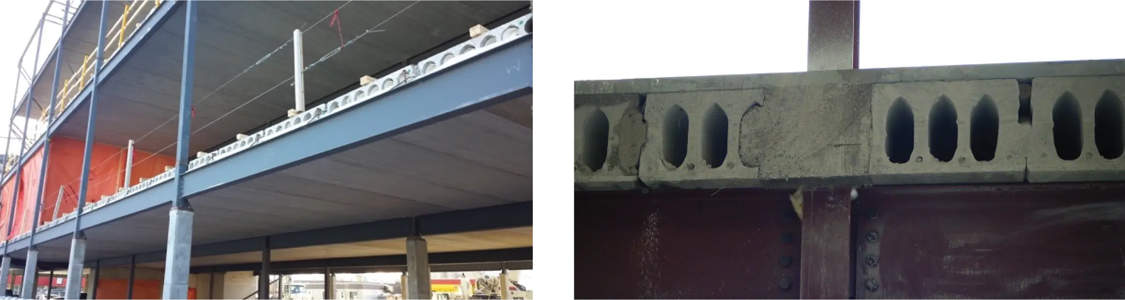
Hollow core slabs consist of precast panels with hollow cells running through the entire panel. Precast concrete panels are built in a factory instead of the concrete being poured at the job site.
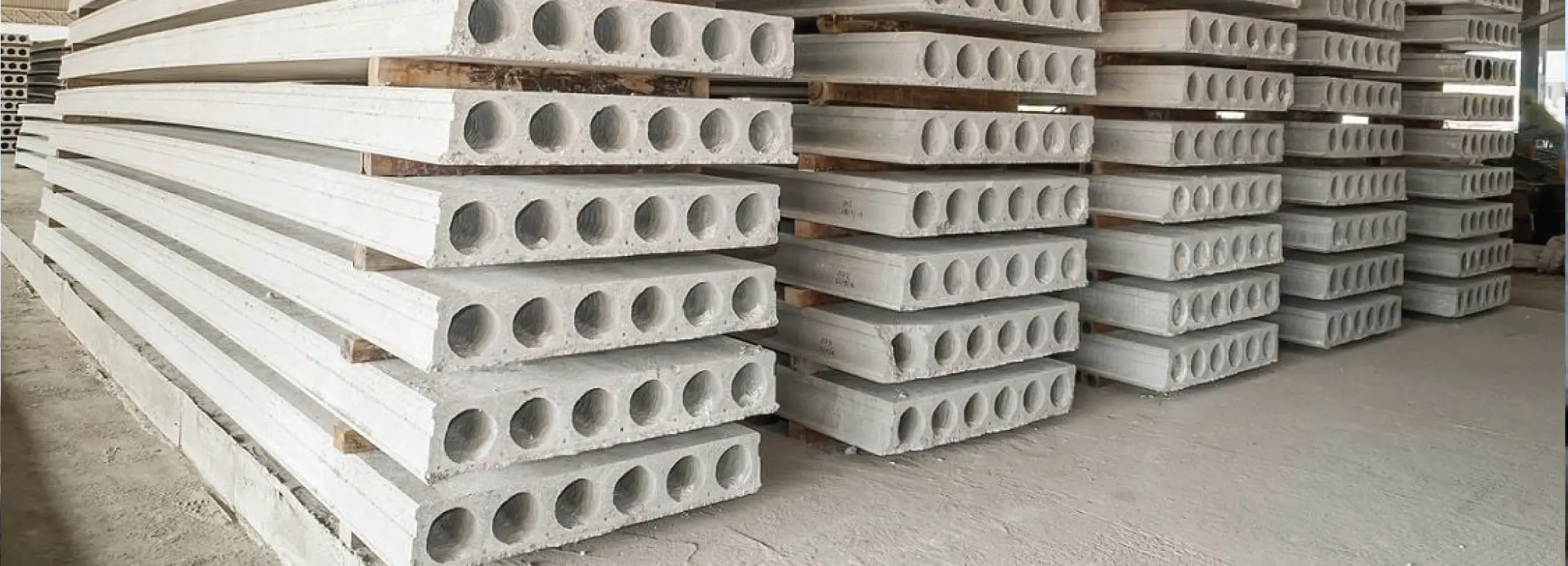
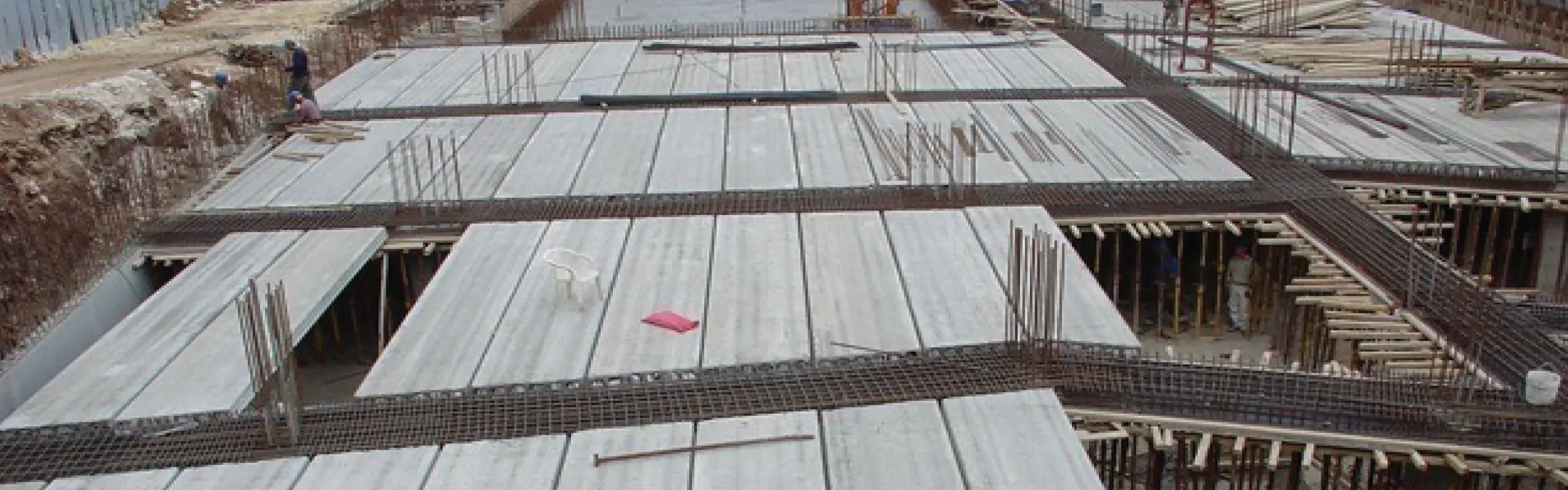
The panels are then brought to the job site and can be set in place by a crane resting them on beams.
HOLLOW CORE COMES IN MANY SHAPES AND SIZES
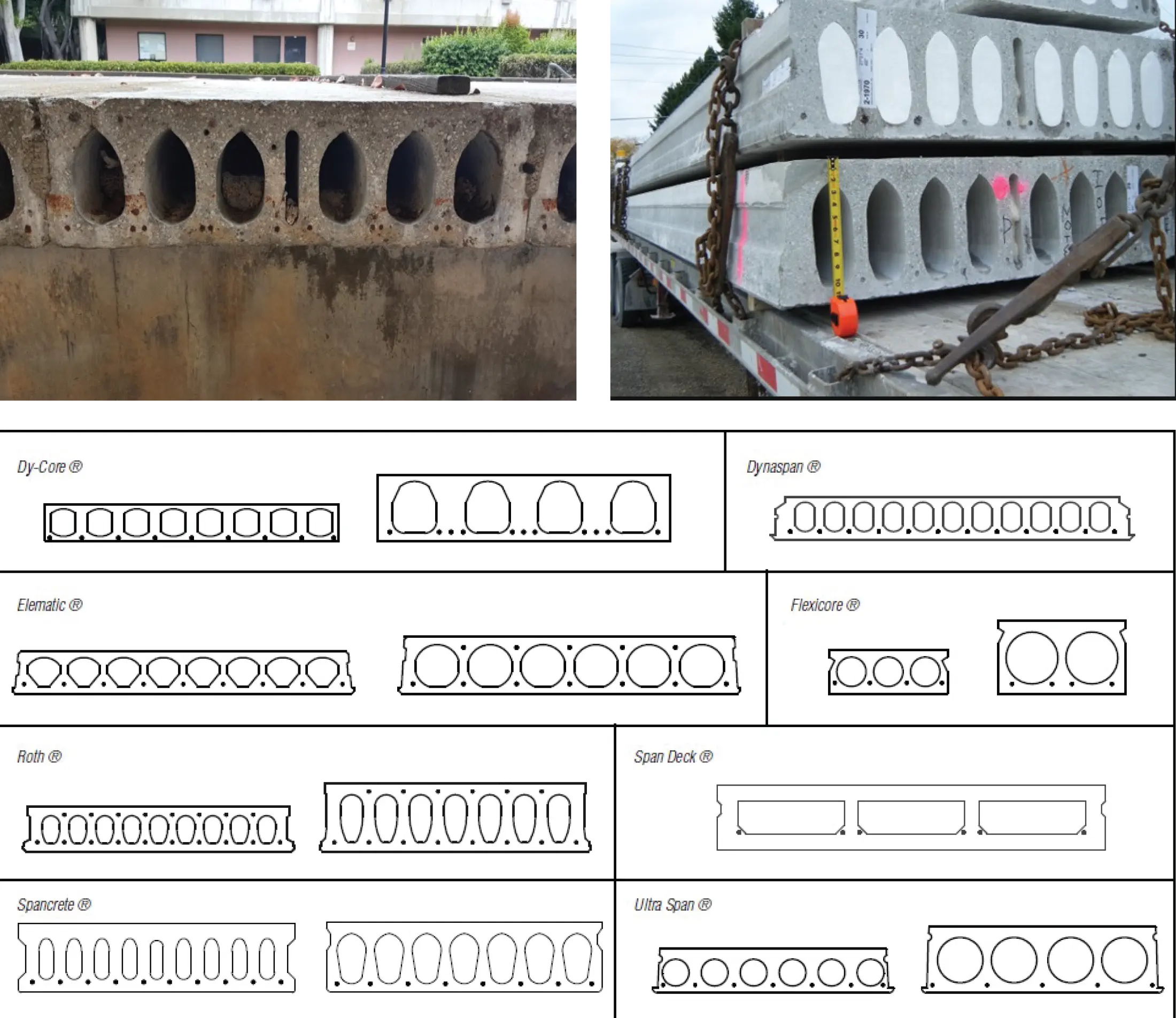
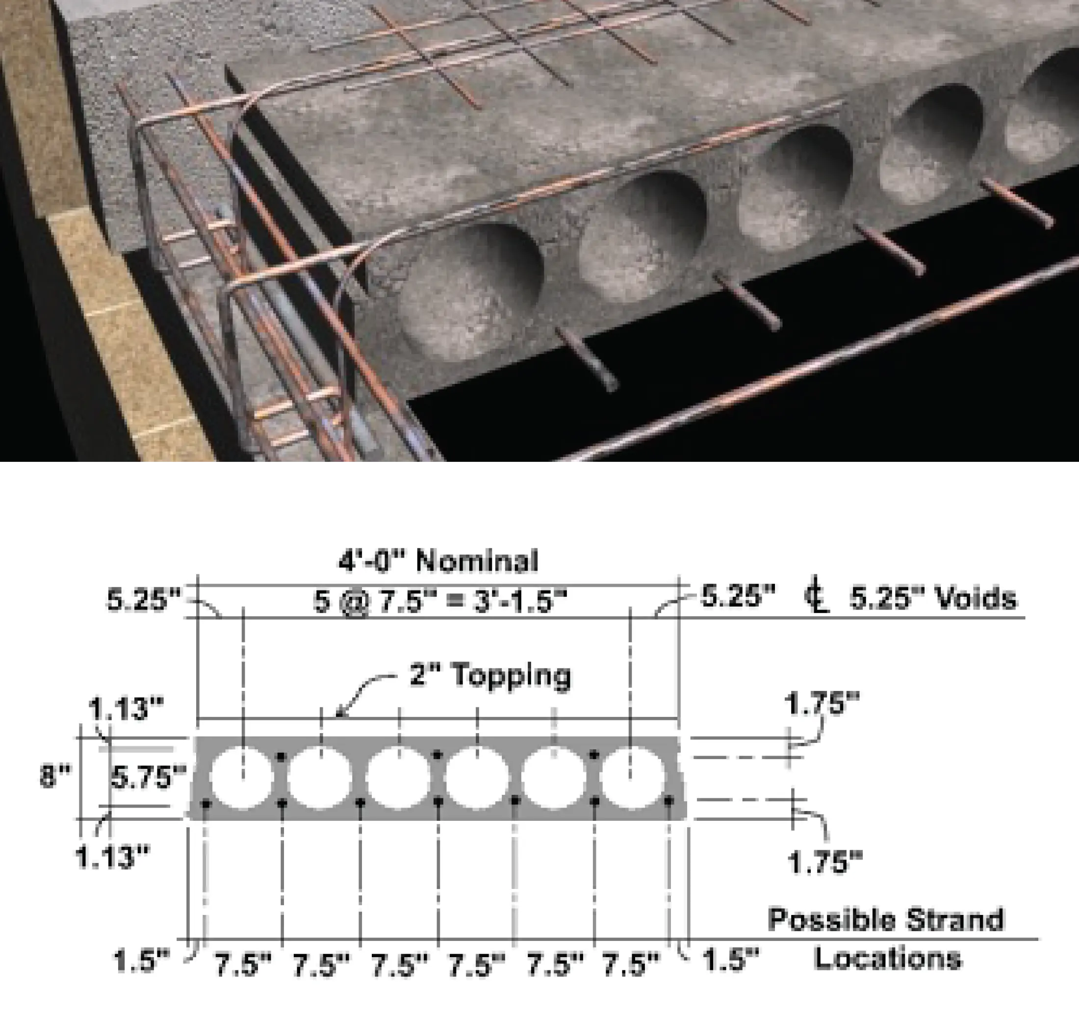
Despite the varying sizes, as can be seen above, what they all have in common is that they have cables positioned between each cell near the bottom of the slab. There will occasionally be cables at the top but still between the cells. We want clients to core drill through the hollow cells, thereby avoiding the cables.
Hollow core slabs will typically have a topping slab over the panels to create a smooth surface. The topping slab will typically contain wire mesh but could have rebar. Wire mesh would not need to be marked out as long as these three steps are followed to verify that it is wire mesh. Confirm perfect spacing (often 6”) for each item, confirm diameters of reinforcing, confirm that all potential mesh disappears during a cross-polarized scan.
INTERPRETING DATA
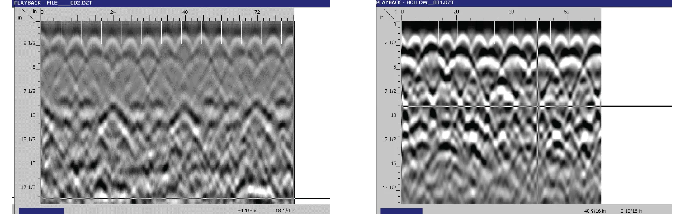
Accurately interpreting data is vital in performing concrete scanning. Below are two examples of very typical hollow core data.
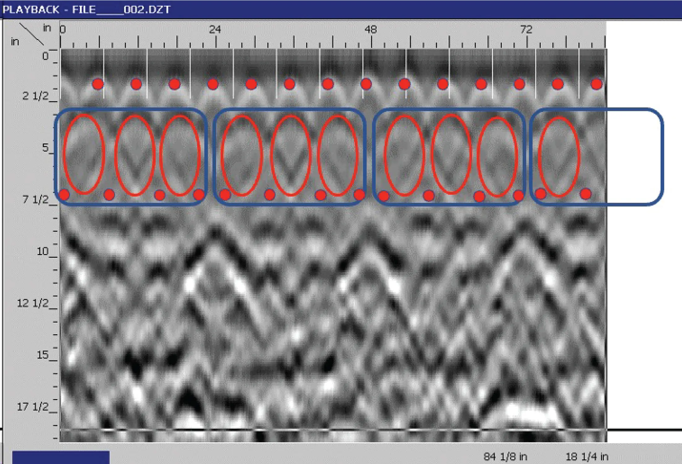
Below is an example of typical hollow core data with the data illustrated. Wire mesh in a topping slab near the top hollows approximately 3” deep. The cables between the hollows are assumed. The cables and the bottom of the slab cannot be and should not be interpreted from this data. Assume that there are cables between each hollow unless the bottom can be scanned to prove otherwise.
HOW TO DIAGNOSE A HOLLOW CORE SLAB
1. Look at the bottom of the slab. You will see a flat bottom with the joints between the panels running in one direction in a uniform spacing.
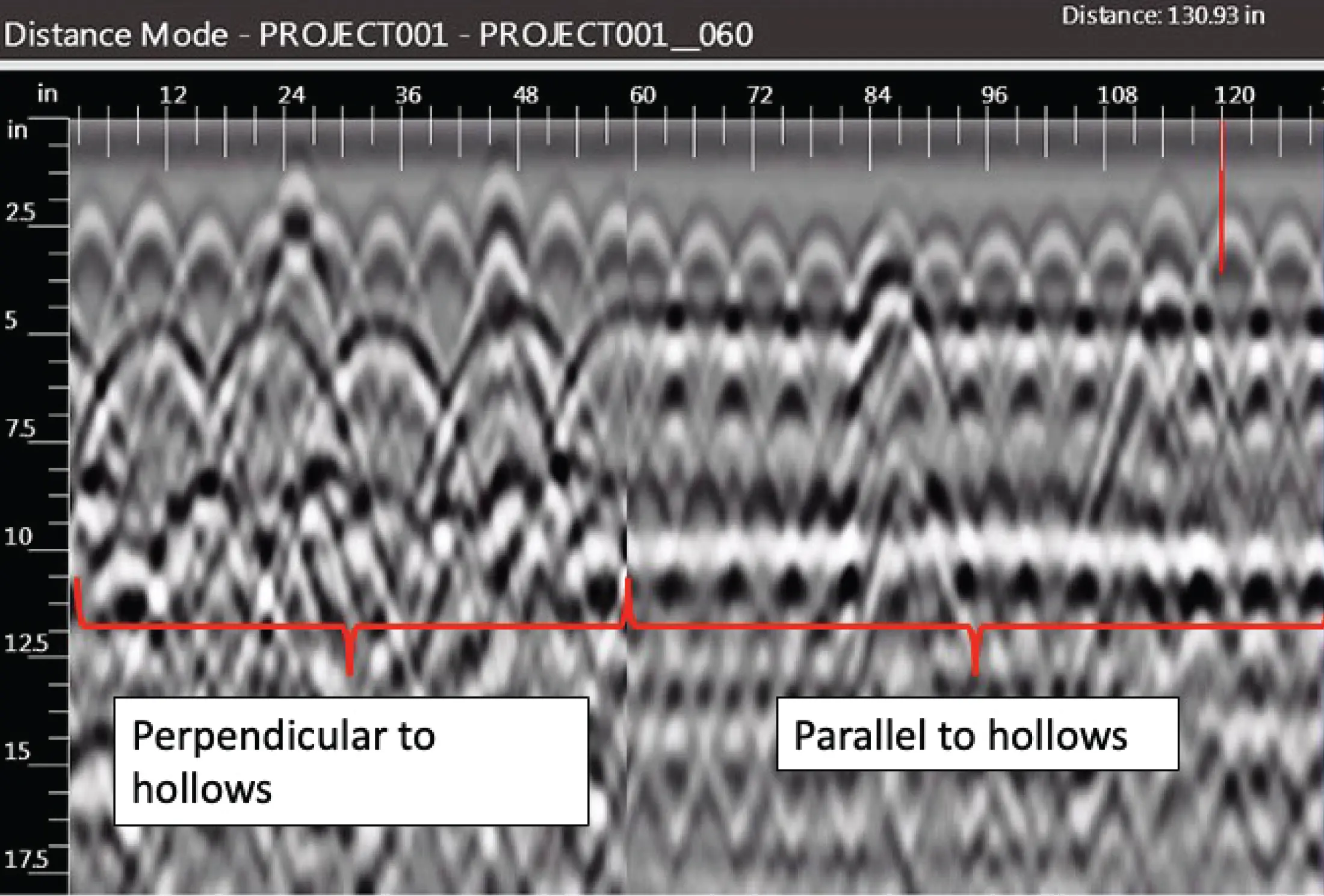
2. Compare both directions. Hollow core is one of the only slabs that will look completely different when scanned in two opposite directions. If you cannot see the bottom, then you should see a near-perfect pattern of non-metallic hyperbola reflections in one direction and a flat, horizontal reflection at that same depth in the opposite direction. A long enough scan should even show a pattern of spacing changes between the peaks due to the joints between the panels, as shown in the first data example in this document.
SCANNING AND MARKING HOLLOW CORE
Hollow core and its variations are the only slab types for which being able to see the bottom of the slab in the GPR data is not necessary. In fact, due to the way the signal passes through the voids, accurately finding the bottom of the slab is not even possible. Since the type of reinforcing and the construction methods for a hollow core panel are known, once the slab is known to be hollow core, all that is left to do is mark out the prestressed cables. Like the bottom of the slab, finding the cables is unnecessary and is not even possible with an adequate level of reliability. But, since their position is known, they can still be marked accurately.
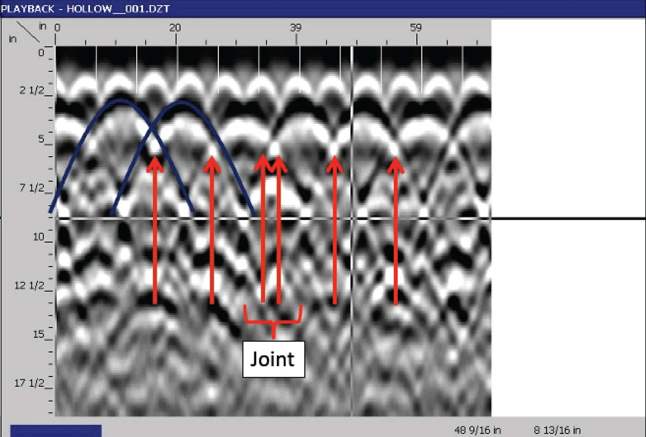
Mark the cables, not the hollows. Rather than marking the center of the hollows and asking the client to drill on the markings or trying to determine how wide the hollows are, mark the cables instead. The cables are known to be below the 1”-1 ½” of concrete between the hollows, and that concrete is known to be centered between the hollows. In the GPR data, the intersections of the tails of the hyperbolas from the hollows will be the exact center between the hollows. Therefore, finding the intersection between the peaks and marking approximately 1” wide is an accurate way to mark prestressed cables. The red arrows indicate the locations that should be marked.
GENERAL CORE DRILLING STANDARD OPERATING PROCEDURE
Mark the cables, not the hollows. Rather than marking the center of the hollows and asking the client to drill on the markings or trying to determine how wide the hollows are, mark the cables instead. The cables are known to be below the 1”-1 ½” of concrete between the hollows, and that concrete is known to be centered between the hollows. In the GPR data, the intersections of the tails of the hyperbolas from the hollows will be the exact center between the hollows.Therefore, finding the intersection between the peaks and marking approximately 1” wide is an accurate way to mark prestressed cables. The red arrows indicate the locations that should be marked.
Pre-Scan
1. Complete work authorization and JHA in Infor
2. Request as-built drawings from the client
3. Walk the site with the client
4. Look at the bottom of the slab
5. Determine whether a report is needed and whether GPR data will need to be saved
6. Update JHA
Scanning
1. Collect long scans to evaluate the slab
2. Identify the bottom of the slab within the GPR data
3. Trace one target at a time in one direction at a time
4. Draw all findings on the surface
5. Check findings with 45° angled scans
6. Cross polarized scans
7. Check accuracy with reference dashes
8. Use a pipe locator to trace conduits/utilities
9. Passive sweep
10. Mark scan boundaries
11. Document findings
Post-Scan
1. Walk the site with the client
2. Job Summary Report
STANDARD OPERATING PROCEDURE DETAILS FOR HOLLOW CORE
• Identify the direction of the hollow core.
• Mark out prestressed cables using cross-polarized scans and mark the intersections of the tails from the hollow core reactions
• Follow general core drilling SOP for topping slab portion
LEARN MORE
GPRS specializes in ground penetrating radar, scanner, video pipe inspection, and mapping and modeling services. Our Project Managers have the equipment and expertise to handle all subsurface challenges presented. GPRS does this by utilizing various equipment paired with their industry-leading SIM process.
