

.svg)
Understanding Decking from a Concrete Scanning Perspective
GPRS is the nation’s largest private subsurface locating company. GPRS is the company that provides concrete scanning, utility locating, leak detection, and video pipe inspection services. Our dedication to safety has helped us achieve an over 99.8% subsurface damage prevention scanning rate on hundreds of thousands of scanning and location projects. GPRS has unparalleled accuracy and as a company, we want to raise the industry standard. To help push the industry forward, GPRS is releasing articles about our training methodology. This article will review our training documentation and methodologies concerning decking.
WHAT IS DECKING?
Decking, also known as pan decking, metal decking, etc., can be used to form slabs, primarily in steel buildings but can also be found in some regions of concrete structures. The decking acts as both the form in which to pour the concrete and most of the structural support for the slab

The shape of the decking gives it strength and allows for slabs that are thinner than a conventional slab. There are many types and sizes of decking, but the most common type is shown here. The slab is usually about 3” thick above the peaks of the decking and 6” thick at the valleys, although these thicknesses can vary.

While the decking shown above is the most common type of decking used, as shown below, decking comes in many styles and sizes.

HOW TO DIAGNOSE A DECKING SLAB
1. Look at the bottom of the slab. If the base can be seen, then the decking pattern will be prominent.

2. Compare both directions. Decking is one of the only slabs that will look completely different when scanned in two opposite directions. If you cannot see the bottom, you should see a nearly perfect pattern of metallic reflections that may look like hyperbolas in one direction and a flat, horizontal reflection at that same depth of the peaks or valleys in the opposite direction.

HOW TO MARK A DECKING SLAB
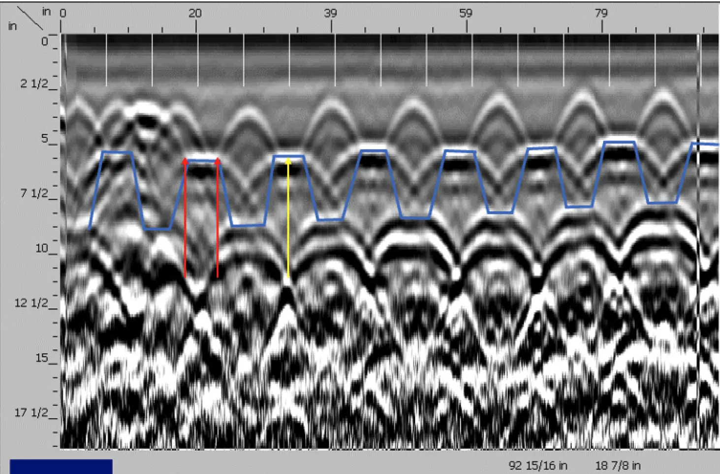
Marking a decking slab begins with marking out the decking's high points (peaks). The low points do not need to be marked within the data because all the areas outside the high point will be treated as low points, including the angled portion. The edges of the high points can be located as shown above by the red arrows. Once a width of the peaks has been established, the rest can be marked by finding the center of the high point and measuring to both sides to create a consistent width, as shown by the yellow arrow.

The high and low points are marked because conduits in a valley of the decking can be very difficult or impossible to see. For these circumstances, we advise drilling only in the high points and that conduits may not be able to be found in the low points. Conduits in the low points are sometimes visible and should be marked out clearly when possible, and this cannot be done clearly when all of the low points are hashed out. Also, a larger core is not possible if the low points are not an option. The client needs to know that they drill at their own risk when drilling through a low point.

Above is an example of what a conduit could look like in the low part of the decking. Look at the reflection from the low points and identify reactions that break the typical pattern. This one may be due to the overlap from the edges of two pieces of the decking, but it would need to be marked as a potential conduit. Anything that breaks the typical pattern in a decking slab should be marked as a conduit unless it can be proved to not be a conduit through further investigation, cross polarizing, etc.
LOCATING BEAMS

Even though the beams cannot usually be located, most beams will be attached to the slab with shear studs, aka Nelson studs. These studs will typically be centered on the beam and 1’ on center or at every low point of the decking. By collecting scans along each of the low points, the studs can be identified, thereby identifying what is assumed to be the center of the beam. The width of the beam cannot be determined.


The Nelson studs are difficult to see here because they are near the same depth as the mesh but are being pointed out by the red arrows. The portion on the right is a scan over one of the studs in the opposite direction. A stud in one location could look similar to a conduit or rebar, but it will not trace out when the scan is moved to one side or another, and when the spot is scanned across in another direction, the reaction will look the same in any direction.

Above is an illustration of the Nelson studs from the previous slide. The scan happened to miss the stud furthest to the right.
GENERAL CORE DRILLING STANDARD OPERATING PROCEDURE
Pre-Scan
1. Complete work authorization and JHA in Infor
2. Request as-built drawings from the client
3. Walk the site with the client
4. Look at the bottom of the slab
5. Determine whether a report is needed and whether GPR data will need to be saved
6. Update JHA
Scanning
1. Collect long scans to evaluate the slab
2. Identify the bottom of the slab within the GPR data
3. Trace one target at a time in one direction at a time
4. Draw all findings on the surface
5. Check findings with 45° angled scans
6. Cross polarized scans
7. Check accuracy with reference dashes
8. Use a pipe locator to trace conduits/utilities
9. Passive sweep
10. Mark scan boundaries
11. Document findings
Post-Scan
1. Walk the site with the client
2. Job Summary Report
Standard Operating Procedure Details for Decking
• Identify the direction of the decking.
• Scan perpendicular to the peaks of the decking (cross-polarized) and mark out the high points
• Label each high point (peak) and low point (valley)
• Follow general core drilling SOP, but scans should be collected parallel to the decking over each peak and valley.
LEARN MORE
GPRS specializes in ground penetrating radar, video pipe inspection, and mapping and modeling services. Our Project Managers have the equipment and expertise to handle all subsurface challenges presented. GPRS does this by utilizing various equipment paired with their industry-leading SIM process.
