

.svg)
Ground Penetrating Radar: Rebar Slabs
GPRS is the nation’s largest private subsurface locating company. GPRS provides concrete scanning, utility locating, leak detection, and video pipe inspection services. Our dedication to safety has helped us achieve an over 99.8% subsurface damage prevention scanning rate on hundreds of thousands of scanning and location projects. GPRS has unparalleled accuracy, and as a company, we want to raise the industry standard. To help push the industry forward, GPRS is releasing articles about our training methodology. This article will review our training documentation and methods concerning dielectrics. Before reading this, we recommend reading our article Basic GPR Theory.
Rebar
Rebar slabs are just cast-in-place slabs that are reinforced with rebar. Cast-in-place means that the concrete is poured onsite in the position that it will remain, as opposed to things like precast panels made in a factory. Forms are placed first as a mold that will form the shape of the slab.The forms will usually consist of bracing below that is supporting plywood. The concrete is poured onto the forms, and the forms are then removed after the concrete is sufficiently cured. Because of this, wood grain and the seams between the plywood are often visible on the surfaces of the concrete that were in contact with the forms.
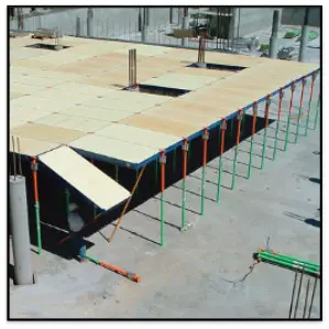
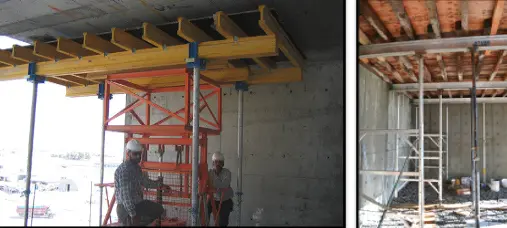
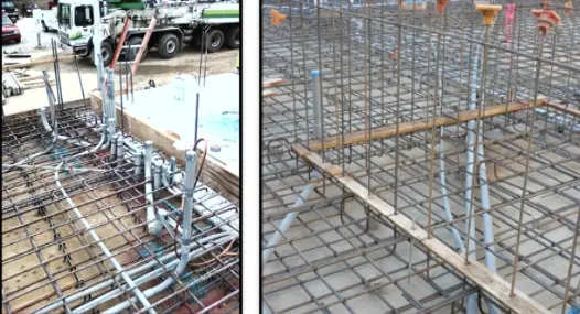
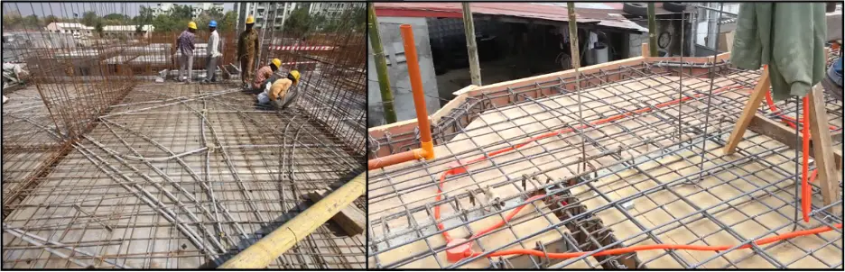
Below are more examples of concrete formwork.
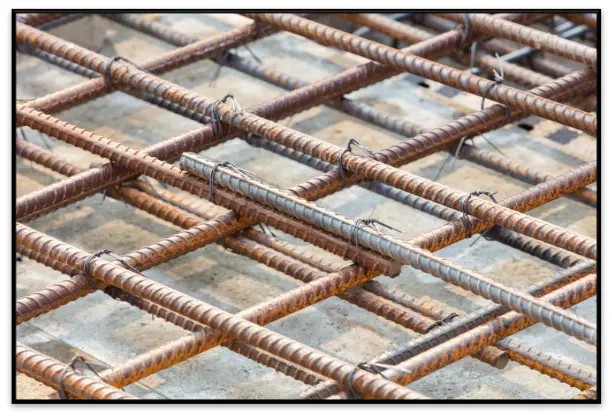
Rebar is reinforcing steel that helps strengthen the concrete to prevent cracking and transfer loads to the proper places. A layer of rebar or grid of rebar is called a mat. Most slabs will have two mats, one near the top of the slab and one near the bottom. The spacing is commonly 10”-12” on the center for each direction of each mat, but this can be more or less than 10”-12” depending on the slab and the area within the slab.
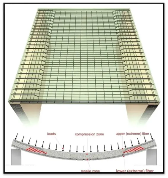
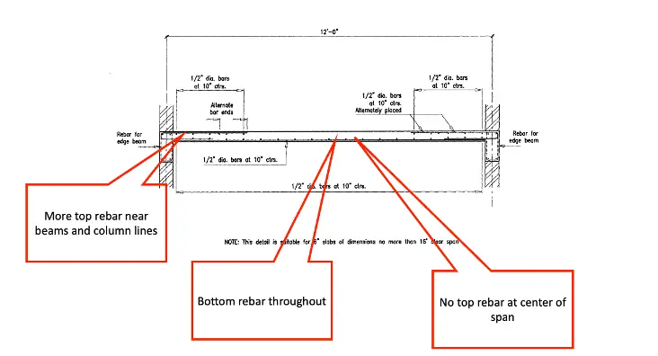
An important concept to understand regarding rebar placement is tension vs. compression. As illustrated in the image to the right, the center of a span between beams or column lines is where the slab will want to sag, and there will be tension at the bottom of the concrete. Concrete has low tensile strength but high compressive strength. Therefore, the rebar placed near the bottom of the slab helps to provide the tensile strength needed in that area. At the beams and column lines, there is tension at the top of the slab.
There will typically be more top rebar and less bottom rebar near columns, column lines, and beams.
There will typically be less top rebar (or none) and more bottom rebar away from the column lines and beams at the center of the span.
There are exceptions to the layout shown in the example below, but this is an example of a prevalent scenario.
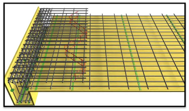
The below image is an example of a typical rebar placement at a beam. This one has no top rebar beyond the beam bars. The bottom rebar is more closely spaced, running perpendicular to the beams and have less running parallel to the beams. If a core is being placed in the area of the top rebar, it can be very helpful to collect scans beyond where the top rebar have ended to obtain a better view through the slab.
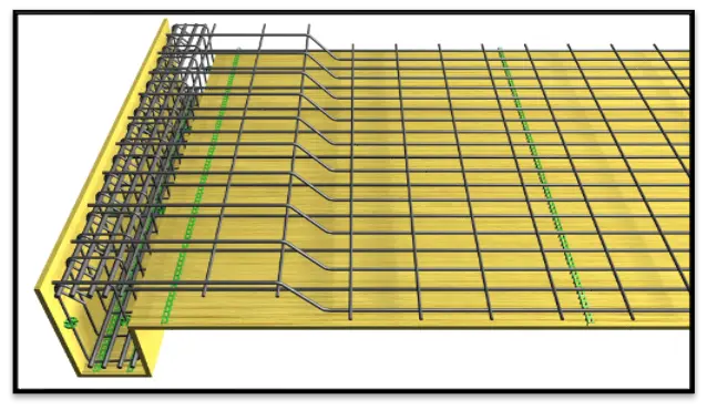
This example below is similar to the previous one except that the bottom rebar are bent and become the top rebar near the beam, leaving half the number of bottom rebar at the beam. This is a fairly common condition. Even if there is less bottom rebar, it should be assumed that there is some bottom rebar throughout the entire slab. If you don’t see the bottom rebar, you cannot be sure that you are seeing the bottom of the slab!
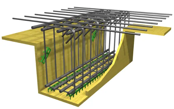
The image below shows how a typical beam is constructed. There will be top rebar extending across the beam into the slab, essential structural rebar running parallel to the beam at the top and the bottom, and stirrups wrapping around the entire beam, forming a cage.
How to Diagnose a Rebar Slab
- Look at the bottom of the slab. Can the results of the formwork be seen? Are there beams? PT beams will often be a different shape than rebar beams.
- Identify a pattern of the top and bottom rebar. The bars should be in a somewhat uniform pattern and spacing and should have two identifiable mats, usually within 1”-3” of the slab's top and bottom.
- Find the bottom of the slab in the GPR data. It should be a negative (black) reflection from the air at the bottom of the slab. It should also be primarily flat due to being formed instead of being poured on soil.
- Once the bottom of the slab is confirmed, always slow down and ask whether it makes sense. Was the bottom rebar confirmed within a few inches of the bottom of the slab? Is the bottom at least 6” deep? The slab should be a minimum of 6” to make sure that it is not actually just a topping slab or a ribbed/waffle slab. 6”-12” will be the most common thicknesses, but the slab can sometimes be much thicker than 12”. Any supposed depth outside of 6”-12” should at least be a red flag, and further investigation or a second opinion may be needed.
Below is an example of typical rebar slab data with two reinforcing layers. The bottom rebar is closely spaced, approximately 6” on center. Its consistency makes it appear at a glance to be wire mesh. This is very important to determine. If the lower layer is wire mesh, then the true bottom of the slab cannot be seen. If the lower layer is rebar, the slab meets the 6” minimum thickness requirement, has bottom rebar, and makes sense. Wire mesh is not structural, and, as previously stated, there should always be bottom rebar identified to ensure that the bottom of the slab is being seen. This could be confirmed as rebar and not mesh using at least these 3 pieces of information: 1) the spacing is not perfect. 2) measure the diameter by comparing the depth in both directions. If it appears to have almost no diameter, then it is wire mesh; if it has a measurable diameter of at least 3/8”, it is rebar. 3) Cross polarize; wire mesh should disappear while rebar should only get dimmer.
Standard Operating Procedures and Markings
Pre-Scan
1. Complete work authorization and JHA in Infor
2. Request as-built drawings from the client
3. Walk the site with the client
4. Look at the bottom of the slab
5. Determine whether a report is needed and whether GPR data will need to be saved
6. Update JHA
Scanning
1. Collect long scans to evaluate the slab
2. Identify the bottom of the slab within the GPR data
3. Trace one target at a time in one direction at a time
4. Draw all findings on the surface
5. Check findings with 45° angled scans
6. Cross polarized scans
7. Check accuracy with reference dashes
8. Use a pipe locator to trace conduits/utilities
9. Passive sweep
10. Mark scan boundaries
11. Document findings
Post-Scan
1. Walk the site with the client
2. Job Summary Report
Conduits in Rebar Slabs
Rebar slabs can sometimes have conduits running inside of the slab. They could run in any direction and at any depth, but they will often be between the top and bottom rebar and will often be resting on the bottom rebar. Older buildings could have metal conduits, but most will be plastic.
As pictured below, conduits will occasionally enter junction boxes that are often embedded in the slab and can and should be identified and marked. The image on the right shows a smurf tube that is more flexible, typically blue plastic. Due to their flexibility, smurf tubing can take even less predictable paths than typical plastic conduits.
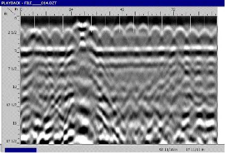
Below is an example of what an embedded electrical box could look like through a GPR scan. It would look the same or very similar when scanning the box in any direction. If a box is found, scans should be taken around it.
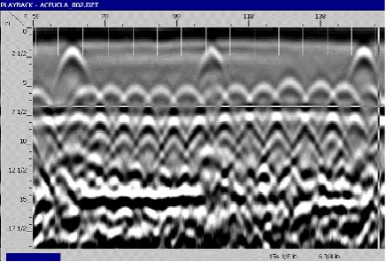
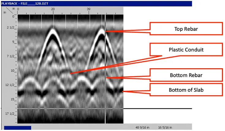
Below is an example of a typical rebar slab.
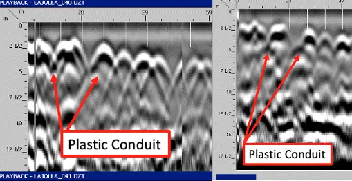
Cross polarizing is crucial for finding plastic conduits.The right image is a cross-polarized version of the left image. One of the conduits in the left image is very difficult to see, and the other is impossible without cross polarizing.
Learn More how GPRS specializes in ground penetrating radar
GPRS specializes in ground penetrating radar, video pipe inspection, and mapping and modeling services. Our Project Manager shave the equipment and expertise to handle all subsurface challenges presented.GPRS does this by utilizing various equipment paired with their industry-leading SIM process.
Visit our website to learn more, or click here to schedule a project with GPRS and allow our highly trained Project Managers to keep your projects on time, on budget, and safe.
