

.svg)
industry insights
Featured Articles
Why Do You Need Updated As-Builts on Your Next Project?
Is Utility Mapping Worth the Cost?
industry insights
How Post-Tensioned Cables Are Anchored In Concrete Slabs
Post-tensioned (PT) slabs are essential in modern construction, especially high-rise construction, because they offer efficiency, durability, and the ability to span longer distances while reducing material usage.
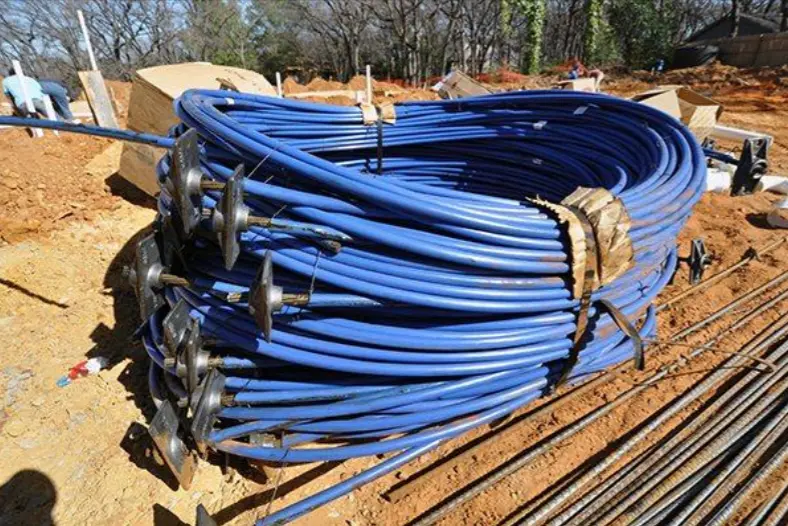
Unlike precast slabs, PT slabs are cast-in-place, meaning the concrete is poured on-site, allowing flexibility in design and construction. Embedded within the slab are post-tensioning cables, made of high-strength steel tendons, which are positioned before the concrete pour and later tensioned. Once the concrete reaches adequate strength (2,500 – 3,000 psi), the cables are anchored and stressed, compressing the slab to enhance its structural integrity. Proper installation and anchoring of PT cables ensure minimal deflection, reduced cracking, and increased load-bearing capacity.
Installation and Sequence of Post-Tensioned Slab Creation
The installation of post-tensioned cables follows a precise sequence to ensure reliable performance. Before any concrete is poured, the post tension tendons are laid out in specific locations and/or patterns. The individual tendons are housed within ducts or sleeves to prevent direct contact with the concrete, to reduce friction during stressing.
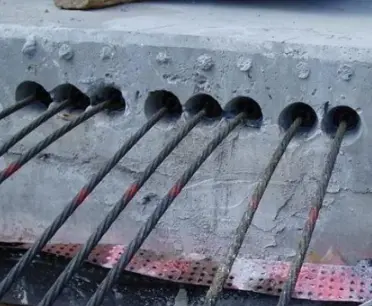
The cables are then anchored at their dead end, where they remain fixed, while the live end is left accessible for later tensioning. These are the “spaghetti ends” you can see emerging from the center of a newly poured PT slab to dangle over the side. In truth, the cable can be tensioned from either side, but the dead end generally arrives already seated in its anchor plate from the manufacturer, which will be grouted and capped after tensioning occurs.
Once the cables are in position – in either a uniform or banded layout – concrete is poured and allowed to cure. The generally required compressive strength for these tendons is 3,500 to 5,000 psi before stressing. Once the concrete has cured, the molds used to frame it are removed and hydraulic jacks are employed at each live end to stretch the tendon to its designed tension level, after which anchors secure the tendons permanently within the slab.
What is the Difference Between Dead End and Live End Anchoring?
Each PT cable features two anchor points:
• The dead end is embedded in the concrete before it is stressed. The dead ends of the tendons are secured by fixed anchor plates, locking them into position to prevent movement.
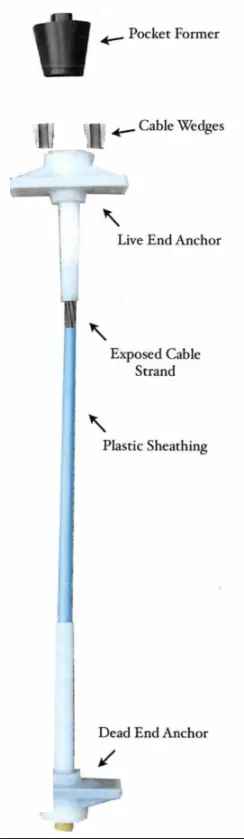
• The live end is where the “magic” happens because that’s where tensioning occurs. Each live end is exposed post-cure, so that the hydraulic jack can pull them to the necessary force before locking them in place. Once the tendons are secured, the stressing pocket is typically grouted or encased in concrete to protect the anchorage system.
Composition and Specifications of PT Cables & Anchors
Post tension cables are engineered to withstand significant tension forces while maintaining flexibility during installation. They are composed of high-strength steel tendons, ranging in diameter from 3/8" to 1/2", and are encased to reduce friction and shield them from corrosion.
Anchor wedges, plates, and encapsulations are integral components of the system, ensuring a secure attachment to the concrete structure. Grout is applied in bonded post-tensioning systems, to provide added durability and prevent destructive moisture intrusion, particularly in applications requiring long-term exposure to environmental elements.
Anchoring Mechanisms and Types of PT Anchors Explained
Anchoring post-tensioned cables requires specialized components to ensure stability and load distribution. At the dead end, fixed anchors secure tendons before tensioning begins, preventing unwanted movement within the slab. The live end allows controlled tensioning, where cables are individually stretched before locking them permanently.
There are several types of PT anchors and components used based on structural requirements.
Pocket formers are devices that form temporary recesses in the concrete to allow for stressing.
Flat plate anchors are frequently used in thin slabs because they offer reliable load distribution while minimizing bulk.
Multi-strand anchors accommodate multiple cables and are common in bridge decks and large-scale concrete structures, due to their need for high-capacity tensioning.
Barrel anchors, which are compact in design, provide effective solutions for space-constrained applications while maintaining performance.
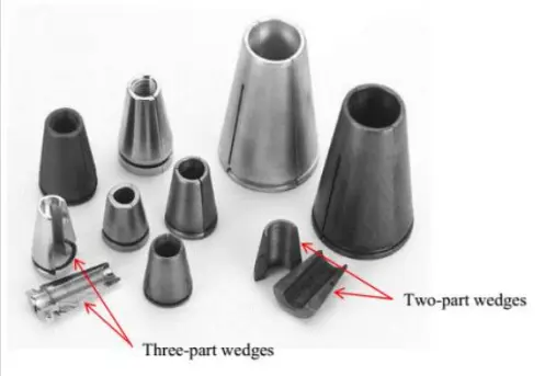
Anchor/Cable Wedges are pieces of tapered, heat-treated, high-strength steel, whose serrations (teeth) penetrate the prestressing steel during the transfer of prestressing force. Anchorage systems sometimes contain two-part or three-part wedges.
Each anchoring method is selected based on load demands, slab thickness, and expected structural movement.
How Do You Reinforce PT Anchors?
Post-tensioned cable anchors experience high localized stresses, so they often require additional reinforcement to maintain stability.
Bursting steel is incorporated around the live-end anchors to mitigate stress concentrations and prevent cracking or failure.
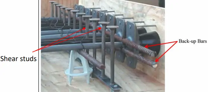
Shear studs enhance anchorage integrity by increasing resistance against movement, especially in applications subjected to dynamic loads.
Back-up bars assist in distributing the force across a broader surface area, reducing stress buildup and improving durability.
Together, these reinforcement strategies ensure the longevity and reliability of post-tensioned slab systems and reduce the risk of long-term degradation.
What Happens After the PT Slab is Tensioned?
When a PT cable is tensioned, it’s generally carrying about 80% of its tensile force. The average PT cable has a tensile strength of 270,000 pounds per square inch (psi). The stressing force for the average ½-inch 270 strand is used, which puts the stressing force at around 33,000 pounds. For comparison, rebar typically yields 60,000 psi.
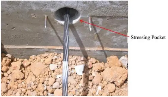
Once tension has been applied to the PT cable, its elongation is measured. A paint mark placed on the cable at end of the slab before it is tensioned allows you to measure the elongation post-tensioning. The area in which this takes place is called the cable’s stressing pocket: the recess created by the pocket that is formed between the stressing or intermediate anchorage and the edge of the concrete that allows nosepiece access for stressing. If you’re checking elongation on the dead end, it is then cut and the pocket grouted over.
Detecting Post-Tensioned Cables Using Ground Penetrating Radar
Ground penetrating radar (GPR) is an effective tool for identifying embedded PT cables within concrete slabs. Unlike the uniform grid-like patterns of rebar reinforcements, post-tensioned tendons display curved profiles, due to their specific placement and stressing process. Anchorage zones, particularly on live ends, generally produce stronger signal reflections. This allows construction engineers and GPRS Project Managers to differentiate between fixed-end anchors, stressing pockets, and the paths of the tendons.
GPR technology is frequently utilized as part of structural assessments, retrofits, and post-construction modifications, to provide contractors accurate locations of all PT slab reinforcements, and to provide safe cutting, coring, and drilling clearances. The cables can also be placed in banded columns for additional reinforcement near pillars and elevator shafts, so it’s vital to know which kind of PT layout you’re dealing with prior to making any cuts into the slab.
The correct anchoring of post-tensioned cables is essential to achieving structural integrity and optimizing the performance of PT slabs. From installation and dead/live end anchoring to reinforcement measures and detection methods, each step in the process plays a critical role in ensuring reliability. Understanding the nuances of post-tensioning is crucial to maximizing efficiency while maintaining compliance with industry standards and keeping work teams safe.
GPRS is the only company in the U.S. that offers the Green Box Guarantee. Since 2017, our Project Managers have maintained a 99.8% accuracy rate in concrete scanning & imaging, so if we mark out a green box that says clear, we guarantee that you will not strike a PT cable or reinforcement. If you do, we’ll pay the material cost to repair it.
Frequently Asked Questions
How does GPR find post tension cables in concrete?
Ground penetrating radar (GPR) is used to locate post tension cables by emitting high-frequency radio waves into concrete and analyzing the reflected signals – that show up on a readout screen as hyperbolas – to identify embedded objects based on their dielectric properties and depth.
Learn more about how GPRS uses GPR, here.
What happens when a post tension cable is accidentally severed?
Severing a post tension cable can cause it to snap back violently due to the high tension, which poses serious safety risks and can compromise the structural integrity of the slab. The average cost to replace a severed post tension cable is between $20,000 and $30,000.
Learn more about GPRS concrete services, here.
Balfour Beatty Breaks Ground on Miami Beach Hotel
GPRS safety partner Balfour Beatty has begun construction on the Grand Hyatt Miami Beach in Florida.
The $385 million construction services contract calls for the delivery of a 17-story, 996,130 s.f. hotel located at the intersection of 17th Street and Convention Center Drive, which will include 800 guestrooms – including 52 suites – as well as convention and meeting space, and ground floor retail areas.
According to a press release issued by Balfour Beatty, the construction company is undertaking the development on behalf of MB Mixed Use Investment, LLC, a partnership between developers Terra Group and Turnberry.
Once complete, the hotel will serve as the central anchor of the Miami Beach Convention Center District, “transforming the city’s convention center campus into a desirable meeting and convention destination worldwide,” the press release states.
“We are excited to partner with Terra Group and Turnberry, two highly regarded developers in South Florida, to deliver this transformative project for the Miami Beach community,” said Scott Skidelsky, Balfour Beatty’s President of Southeast Buildings Operations. “This project further strengthens our diverse business portfolio in South Florida, where hospitality continues to be an anchor market sector throughout Florida. We look forward to leveraging the experience of our South Florida team, who bring extensive expertise in the successful delivery of high-rise projects, hospitality and convention spaces.”

Construction on Grand Hyatt Miami Beach is scheduled for completion in late 2027. Balfour Beatty says the project will employ more than 500 workers at peak construction.
The hotel will feature a resort-style pool deck with panoramic views, five food and beverage outlets including a signature restaurant, a lobby lounge and bar, and fitness and spa facilities. The hotel’s design is being overseen by Arquitectonica and includes a podium with retail and restaurant spaces at street level and a covered drop-off area accessible from two streets.
According to the Miami Beach Convention Center website, the hotel is positioned “to integrate harmoniously with surrounding landmarks such as the New World Symphony and the Miami Beach Botanical Garden.”
“Grand Hyatt Miami Beach is a major investment in our city’s future – bringing jobs, quality year-round tourism, and long-term economic growth,” Miami Beach Mayor Steven Meiner told the MBCC. “Miami Beach remains a sought-after destination for its beauty and growing reputation as a safe, strong, and sophisticated city. This groundbreaking is further evidence that investor confidence in Miami Beach has never been higher.”
“This is a defining moment for our convention and trade show eco system,” added David Whitaker, President & CEO of the Greater Miami Convention & Visitors Bureau (GMCVB). “Grand Hyatt Miami Beach will further strengthen our ability to compete for premier meetings, trade shows and conventions by offering a level of integration and convenience that meeting planners increasingly value. With direct access to our state-of-the-art Miami Beach Convention Center and the vibrant energy of Miami Beach just steps away, this hotel adds an exciting new dimension to the experience we offer.”
According to reporting by Engineering News-Record, funding for the project is being supported, in part, by a $75 million grant awarded through the Miami Beach Redevelopment Agency in late 2024.
Balfour Beatty was selected to construct the hotel in 2023. The firm recently celebrated the completion of the $1.2 billion Broward Convention Center & Hotel and expansion project.
“The company's reputation as a premier hospitality builder in Florida as well as its continued commitment to delivering transformative projects that enhance communities throughout the state were key factors in being selected for this development [in Miami Beach],” Balfour Beatty said in its press release. “Balfour Beatty brings significant hospitality and convention center expertise to the project…”
Whether you’re building a luxury resort in the Sunshine State or a 60,000-seat football stadium in New York State, GPRS supports your construction projects through our comprehensive suite of subsurface damage prevention, existing conditions documentation, and construction & facilities project management services. We offer precision concrete scanning and utility locating, pinpoint-accurate leak detection, NASSCO-certified sewer line inspections, 2-4mm accurate 3D laser scanning, and in-house mapping & modeling tailored to your project’s specific needs.
All this accurate, actionable data is at your fingertips 24/7 thanks to SiteMap® (patent pending), GPRS’ project & facility management application that provides accurate existing conditions documentation to protect your assets and people.
From skyscrapers to sewer lines, GPRS Intelligently Visualizes The Built World® to help keep you on time, on budget, and safe.
What can we help you visualize?
Frequently Asked Questions
Will I need to mark out the utilities that GPRS locates?
GPRS will locate and mark all utilities for you. We have a variety of tools and markers we can use to highlight the locations of utilities, underground storage tanks and whatever else may be hiding.
What is the difference between a design intent and as-built model?
DESIGN INTENT – deliverables will be shown as a "best fit" to the point cloud working within customary standards, such as walls being modeled 90 degrees perpendicular to the floor, pipes and conduit modeled straight, floors and ceilings modeled horizontal, and steel members modeled straight. This will produce cleaner 2D drawings and will allow for easier dimensioning of the scan area. The deliverables will not exactly follow the scan data to maintain design intent standards. Most clients will want this option for their deliverables.
AS-BUILTS – deliverables will be shown as close as possible to actual field capture. If walls are out of plumb, pipes and conduit show sag, floors and ceilings are unlevel, steel members show camber, etc., this will be reflected in the model. This will produce reality-capture deliverables, but 2D drawings may show “crooked” or out of plumb lines, floors will be sloped or contoured, steel members may show camber, twisting or impact damage. Dimensioning will not be as easy due being out of plumbness/levelness, etc. This option should be used when the exact conditions of the scan area is imperative. Clients using the data for fabrication, forensic analysis, bolt hole patterns, camber/sag/deformation analysis, and similar needs would require this option.
How Sound-Absorbing Acoustic Concretes are Leading a Quiet Revolution in Building Materials
There’s an innovation quietly making waves in the world of construction and materials science.
Sound-absorbing acoustic concrete has emerged as a promising solution for managing noise in urban environments, public infrastructure, and even residential spaces. While concrete has long been valued for its strength and durability, its acoustic properties have traditionally been a drawback. The high density and typically smooth surface of concrete walls and floors block sound transmission but struggle to absorb sound, leading to echoes and reverberations in enclosed spaces.
Now, researchers and engineers are reimagining concrete not just as a structural material, but as a tool for sound control.
What Is Acoustic Concrete?
Also known as sound-absorbing concrete, acoustic concrete is specially engineered and designed to reduce noise by absorbing sound waves rather than reflecting them.
Unlike traditional concrete, which tends to bounce sound back into the environment, acoustic concrete incorporates materials and design features that trap and dissipate sound energy.
This makes it particularly useful in settings where noise pollution is a concern, such as highways, tunnels, train stations, airports, schools, and office buildings.
How Does Acoustic Concrete Work?
The sound-absorbing properties of acoustic concrete are achieved through a combination of material composition and structural design. Some key components of its structure are porosity, additive and aggregated materials, the level of perforation, and layered designs.
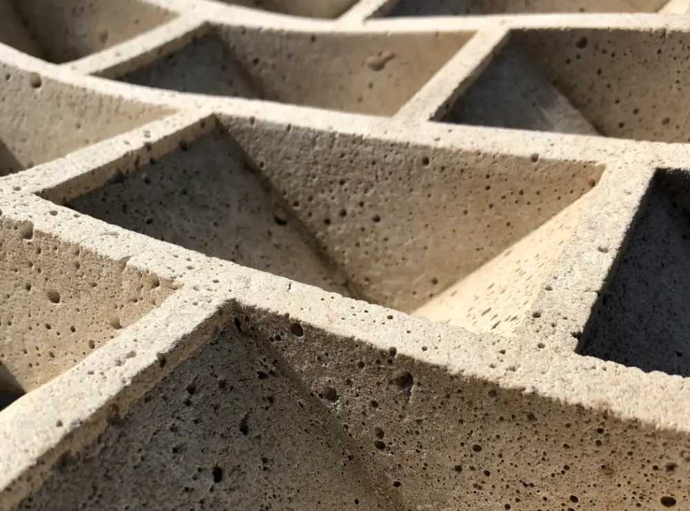
1. Porosity and Surface Texture
One of the key principles behind acoustic concrete is porosity. By introducing air voids or pores into the concrete matrix, sound waves can enter the material and lose energy as they bounce around within the pores. This process, known as sound attenuation, reduces the amount of noise that is reflected back into the environment.
The surface texture also plays a role. Rough or irregular surfaces scatter sound waves, further reducing their intensity.
2. Additives and Aggregates
Acoustic concrete often includes lightweight aggregates such as expanded clay, perlite, or recycled rubber. These materials not only reduce the density of the concrete but also enhance its ability to absorb sound. Some formulations also incorporate fibers or polymeric materials to improve acoustic performance.
3. Perforated or Layered Structures
In some applications, acoustic concrete is used in layered systems or combined with perforated panels. These designs create cavities or air gaps behind the concrete surface, which act as resonators to absorb specific frequencies of sound – particularly low-frequency noise – which is typically harder to manage.
What Are the Applications of Acoustic Concrete?
The versatility of acoustic concrete makes it suitable for a wide range of applications:
- Highway Noise Barriers: Acoustic concrete panels are used along highways to reduce traffic noise for nearby residential areas.
- Tunnels and Underpasses: These enclosed spaces can amplify sound. Acoustic linings help dampen echoes and improve safety.
- Public Transit Infrastructure: Train stations and subways benefit from reduced reverberation, improving both comfort and communication.
- Architectural Design: In schools, offices, and auditoriums, acoustic concrete can be integrated into walls or ceilings to enhance sound quality and reduce distractions.
- Industrial Facilities: Factories and plants use acoustic concrete to manage machinery noise and protect worker hearing.
Benefits and Limitations
Benefits
- Noise Reduction: The primary benefit is, of course, improved sound control.
- Durability: Like traditional concrete, acoustic variants maintain high strength and weather resistance.
- Fire Resistance: Unlike some synthetic acoustic materials, concrete is non-combustible.
- Sustainability: Some formulations use recycled materials, contributing to greener construction practices.
Limitations
- Cost: Acoustic concrete can be more expensive than standard concrete due to specialized materials and manufacturing processes.
- Weight: While some versions are lightweight, others may still be heavy, limiting their use in certain structures.
- Design Complexity: Achieving optimal acoustic performance often requires precise engineering and testing.
Current State of Innovation
The field of acoustic concrete is still evolving, with ongoing research focused on improving performance, reducing costs, and expanding applications.
Advanced Materials
Researchers are experimenting with nano-materials, bio-based additives, and 3D-printed structures to enhance sound absorption. These innovations aim to fine-tune the acoustic properties while maintaining structural integrity.
Smart Acoustic Panels
Some companies are developing modular acoustic concrete panels that can be easily installed and replaced. These panels may include embedded sensors to monitor environmental conditions or structural health.
Sustainability Integration
There’s growing interest in combining acoustic performance with environmental sustainability. For example, using recycled rubber or plastic waste as aggregates not only improves sound absorption but also diverts waste from landfills.
Urban Planning and Policy
Cities are beginning to incorporate acoustic concrete into noise mitigation strategies. In Europe and parts of Asia, regulations either encourage or mandate the use of sound-absorbing materials in new infrastructure projects.
The Road Ahead
As urbanization continues and noise pollution becomes a more pressing concern, the demand for effective and durable sound-absorbing materials is likely to grow. Acoustic concrete offers a compelling solution that blends functionality, resilience, and innovation.
While challenges remain – particularly around cost and scalability – the trajectory of research and development suggests that acoustic concrete will play an increasingly important role in the built environment. Whether it’s making cities quieter, classrooms more focused, or factories safer, this material is helping to shape a more acoustically conscious future.
No matter how soundproof your concrete is, you need to know what’s embedded inside before you cut or core into it.
GPRS ensures the safety of your concrete coring and cutting projects by offering 99.8%+ accurate concrete scanning services that keep you on time, on budget, and safe. We utilize ground penetrating radar (GPR) scanning to find rebar, conduit, post tension cable, and anything else that, if struck by a saw or drill, could have costly and even dangerous consequences.
We are so confident in our SIM-qualified Project Managers that we introduced the Green Box Guarantee, which states that when GPRS places a Green Box within a layout prior to anchoring or coring concrete, we guarantee that the area will be free of obstructions.
If the area isn’t free of obstructions, GPRS will pay the material cost of the damage.
GPRS Intelligently Visualizes The Built World® to keep you on time, on budget, and safe.
What can we help you visualize?
Frequently Asked Questions
What types of concrete scanning are there?
GPRS provides two specific but different scanning services: elevated concrete slab scanning and concrete slab-on-grade locating. Elevated concrete slab scanning involves detecting embedded electrical conduits, rebar, post-tension cables, and more before core drilling a hole through the slab. Performing a concrete slab-on-grade locating service typically involves scanning a trench line for conduits before conducting saw cutting and trenching to install a sanitary pipe, water line, or something similar.
How is GPR used to identify tendons vs. rebar in a post-tensioned slab?
In post-tensioned structures, we typically find one mat of support rebar near the base of the slab. This mat is generally consistently spaced and remains at a constant elevation. Post-tension cables are generally found above this support mat and “draped” throughout the rest of the structure. The elevation of the cable is usually high near the beams and column lines and drapes lower through the span between beams and column lines. Knowledge of these structural differences allows us to accurately differentiate between components. Our Project Managers will leave you feeling confident in our findings and in your ability to drill or cut without issue.
Net Zero Explained
The term "net zero" has become increasingly prominent in discussions about climate change, sustainability, and corporate responsibility.
Governments, businesses, and organizations around the world have made commitments to achieve net zero emissions by various target dates, often by mid-century.
But what does "net zero" actually mean – and why has it become such a central concept in environmental and economic planning?
What Is Net Zero?
At its core, net zero refers to the balance between the amount of greenhouse gases (GHGs) emitted into the atmosphere and the amount removed from it. Achieving net zero means that any emissions produced are offset by an equivalent amount of emissions removed, resulting in no net increase in atmospheric GHG levels.
The most commonly discussed greenhouse gas in this context is carbon dioxide (CO₂), but net zero targets often include other gases such as methane (CH₄) and nitrous oxide (N₂O), which also contribute to global warming.

The Net Zero Equation
To reach net zero, entities must either:
- Reduce emissions through cleaner technologies, energy efficiency, and behavioral changes, and/or
- Remove emissions using natural or technological solutions, such as reforestation or carbon capture and storage (CCS).
Why Net Zero?
The idea of net zero gained prominence following the Paris Agreement in 2015, where nearly 200 countries agreed to limit global warming to well below 2°C above pre-industrial levels, with efforts to limit it to 1.5°C.
Scientific assessments, including those by the Intergovernmental Panel on Climate Change (IPCC), suggest that achieving net zero CO₂ emissions by around 2050 is essential to meet these temperature goals.
Motivations for pursuing net zero vary. For some, it is a response to environmental concerns and scientific consensus. For others, it is driven by regulatory requirements, investor expectations, or reputational considerations.
How Is Net Zero Achieved?
Achieving net zero typically involves a combination of strategies:
Emission Reductions
This is the first and most critical step. It includes:
- Transitioning to renewable energy sources like wind, solar, and hydroelectric power
- Improving energy efficiency in buildings, transportation, and industry
- Electrifying transportation and reducing reliance on fossil fuels
- Modifying agricultural practices to reduce methane and nitrous oxide emissions
Carbon Removal
Once emissions are minimized, remaining emissions can be offset through:
- Natural solutions: Planting trees, restoring wetlands, and improving soil management to absorb CO₂.
- Technological solutions: Direct air capture (DAC), bioenergy with carbon capture and storage (BECCS), and other emerging technologies.
Carbon Offsetting
Organizations may purchase “carbon credits” from verified projects that reduce or remove emissions elsewhere. While controversial in some circles, offsets are often used as a transitional tool when direct reductions are not feasible.
Net Zero vs. Carbon Neutral
While often used interchangeably, net zero and carbon neutral are not identical.
Carbon neutrality typically refers to offsetting emissions without necessarily reducing them, whereas net zero emphasizes deep reductions first, with offsets used only for residual emissions.
Additionally, net zero often includes all greenhouse gases, not just CO₂, and considers entire value chains, including indirect emissions from suppliers and product use.
Who Is Committing to Net Zero?
A wide range of entities have made net zero pledges:
- Countries: Over 140 countries, including major emitters like China, the U.S., and the EU, have announced net zero targets.
- Corporations: Thousands of companies, from tech giants to manufacturers, have set net zero goals, often aligned with science-based targets.
- Cities and regions: Local governments are also adopting net zero frameworks to guide urban planning and infrastructure development.
These commitments vary in scope, ambition, and timelines, and are often accompanied by detailed roadmaps and interim targets.
Challenges and Criticisms
Despite its widespread adoption, the net zero concept is not without challenges and criticisms:
Implementation Complexity
Achieving net zero requires systemic changes across energy, transportation, agriculture, and industry. It involves technological innovation, policy support, and significant investment.
Reliance on Offsets
Critics argue that over-reliance on carbon offsets can delay meaningful emission reductions. The quality and permanence of some offset projects are also questioned.
Equity and Justice
There are concerns about how net zero strategies affect different populations. For example, land use for carbon removal could impact food security or indigenous rights. Ensuring a "just transition" is a key consideration.
Accountability and Transparency
Not all net zero pledges are created equal. Some lack clear definitions, interim targets, or verification mechanisms, leading to accusations of "greenwashing."
The Role of Innovation
Innovation plays a crucial role in enabling net zero transitions. Advances in battery storage, hydrogen fuel, carbon capture, and digital monitoring tools are helping to make net zero more achievable and cost-effective. Continued research and development will be essential to address hard-to-abate sectors like aviation, cement, and steel.
Looking Ahead
Net zero is likely to remain a central framework in climate and sustainability discussions for the foreseeable future. As more entities adopt net zero goals, the focus is shifting from pledges to progress – from setting targets to demonstrating measurable outcomes.
The path to net zero is complex and evolving. It involves trade-offs, uncertainties, and diverse perspectives. Whether viewed as a necessary response to climate science or a strategic business decision, net zero represents a significant shift in how societies think about emissions, growth, and responsibility.
GPRS services are designed to support your efforts to achieve net zero, ensuring the success of green construction projects and other related endeavors by mitigating the risks of subsurface damage whenever you need to break ground.
Our precision concrete scanning and utility locating services utilize ground penetrating radar (GPR) and electromagnetic (EM) locating technologies to provide you with a comprehensive understanding of the infrastructure below-ground and embedded within your concrete slabs. We’ve achieved and maintained an industry-leading 99.8%+ accuracy rating on the over 500,000 concrete scanning and utility locating jobs that our SIM-certified Project Managers have completed since our founding in 2001. So, when you hire GPRS, you’re getting a professional concrete scanning and utility locating company that you can trust to keep your projects on time, on budget, and safe.
All the field-verified data we collect for you is at your fingertips 24/7 thanks to SiteMap® (patent pending), our intuitive infrastructure mapping software application that enables seamless communication and collaboration. Available on any computer, tablet, or smartphone, SiteMap allows for the easy, yet secure sharing of vital infrastructure information within your project team, allowing you to plan, design, manage, dig, and ultimately build better.
From skyscrapers to sewer lines, GPRS Intelligently Visualizes The Built World® to keep your projects on time, on budget, and safe.
What can we help you visualize?
Frequently Asked Questions
What are the benefits of concrete scanning?
Hiring a professional concrete scanning company like GPRS prior to cutting or coring through a concrete slab helps mitigate the risk of damaging any subsurface infrastructure when you do cut or core. This helps keep your project on time, on budget, and safe.
What is the difference between scanning an elevated concrete slab, and a concrete slab-on-grade?
Elevated concrete slab scanning involves detecting embedded electrical conduits, rebar, post tension cables, and other subsurface impediments before core drilling a hole through the slab. Performing precision concrete scanning on a concrete slab-on-grade typically involves scanning a trench line for conduits before conducting saw cutting and trenching to install a sanitary pipe, water line, or other, similar utility.
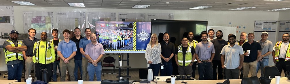
Construction Safety Week 2025: Helping Thousands Stay Safe
The question, “What is your personal safety plan?” has been asked of tens of thousands of construction workers by our GPRS team during Construction Safety Week (CSW) talks across the United States.
At GPRS, safety is our top priority and one of our core values as a company. Because of this, we were so proud to once again sponsor Construction Safety Week in 2025.
In our sixth year as a CSW sponsor, we had the pleasure of meeting with some of the largest general contractors in the nation, including:
- Turner Construction
- Skanska
- Balfour Beatty
- DPR Construction
- Swinerton
- IMC Construction
- Manhattan Construction
- Shook Construction
- AECOM Hunt
- Hunt/Moss
- Brasfield & Gorrie and more!
GPRS Sales Leader Dave Mulcahey had this to say about the week:
“GPRS was proud to sponsor and serve another Construction Safety Week this year. We had the ability to align with many of our national partners in safety and visited so many major jobsites all across the country. We will continue to preach safety in our pursuit of 100% damage prevention, and for us to go home safely every day."
ALL IN TOGETHER
This year’s theme was to PLAN, OWN and COMMIT to safety because we are All In Together. By going All In Together on safety, everyone can work as one with the same goal in mind.
The three pillars of this year’s safety week - Plan, Own & Commit - all have their own purpose and meaning:
- PLAN: Plan each job with precision, purpose, and determination to keep everyone working together and without risk of injury
- OWN: Own your part in the team’s safety and success, so everyone’s voice can be heard and you can build a culture of trust and respect
- COMMIT: Commit fully to executing with excellence to make your team safer and stronger
CSW BY THE NUMBERS
By the end of Construction Safety Week 2025, the GPRS team engaged with over 12,000 attendees at 147 job sites across the country.
At these talks, our team of safety experts imparted essential knowledge and best practices to help each team member on a job site develop a personal safety plan. Our safety experts also brought breakfast or lunch with them for the crews to help keep team members well-fed and engaged.
Since becoming a CSW sponsor in 2020, our team at GPRS has helped more than 65,000 workers develop personalized safety plans tailored to handle many scenarios they might encounter onsite.
WHY CSW MATTERS
What is talked about and taught during Construction Safety Week is meant to last much longer than seven short days in May. When safety is a top priority on a job site, workers are happier, healthier, and go home at the end of every workday.
Attendees were given the opportunity to cultivate and enhance safety cultures that they can bring back to their team. Attendees’ personal safety plans revolved around:
- Underground utility strikes, and best practices to prevent them
- Heat related illnesses, how to prevent them before they occur, and other climate related risks
- Wearing proper PPE when saw cutting, coring, or drilling through concrete
- Climate related risks on site
- The effects of workers’ mental health on safety and preparedness on the job
LOOKING FORWARD
Construction Safety Week 2025 may now be behind us, but our commitment to safety at GPRS never stops.
Along with CSW, GPRS also sponsors two other major safety events: Water & Sewer Damage Awareness Week in the fall and Concrete Sawing & Drilling Safety Week in the winter. Stay tuned for opportunities to increase your site safety by signing up early for either of these talks!
At GPRS, our mission is to help you Intelligently Visualize The Built World® and keep your projects on budget, on time, and safe. To learn how we can do just that, schedule a service or request a quote today!
Facility Condition Assessments: A Data-Centric Approach to Proactive Maintenance and Risk Mitigation in CRE
Facilities managers in commercial real estate (CRE) oversee complex portfolios of aging assets, regulatory burdens, and operational demands. While you have many tools at your disposal to effectively run operations, few are as valuable as an accurate facility condition assessment (FCA).

FCAs are not process exercises; they are foundational to strategic facility asset management. When correctly integrated into an operational & maintenance strategy, FCAs allow you to take a proactive approach to maintenance, facilitate risk mitigation measures, and ensure efficient resource allocation. And they are essential to enacting any kind of predictive maintenance strategy.
However, none of that can happen unless you start with precise, comprehensive existing conditions data - aboveground and below – that informs your team, stakeholders, and other decision-makers to act, rather than react, in planning, upgrading, retooling, and managing facilities. This proactive approach is scalable and can be applied to one facility or hundreds because it is built on data standardization and accuracy.
Transitioning from Reactive to Proactive Maintenance
Reactive maintenance is often described as “run-to-failure” because you do not act until trouble arises. On its face, it may appear to provide short-term cost effectiveness, but in reality, it leads to higher long-term operational costs and increased exposure to unplanned asset failures. It is more like trying to close a gaping wound with a Band-Aid. You patch, and reallocate, and patch again, until the dam breaks and so does the system. Then you’re facing large-scale, rolling breakdowns that result in expensive emergency repairs, tenant dissatisfaction, code violations, and shortened asset life cycles, not to mention the damage that can be done to your reputation.
The reactive model keeps you racing to make up for resource inefficiencies and limits your ability to forecast realistic capital needs. Plus, it’s just simple common sense to realize that it requires a lot more effort to run from disaster to disaster than it does to have plans & processes in place to manage disaster before it strikes.
Proactive maintenance, in contrast, uses the data you gain by adopting an FCA to guide scheduled interventions, optimize part replacements, and extend the service life of physical assets. Facilities managers who adopt a data-informed maintenance strategy are positioned to significantly reduce lifecycle costs and better align operational budgets with actual asset performance requirements. This could enable your budgetary needs to gain priority because you are able to present a measured, data-backed case for funds, rather than approaching those holding the purse strings, hat in hand, with your hair on fire thanks to the latest facility or asset failure.
What is the Difference Between Proactive Maintenance and Predictive Maintenance?
While both proactive and predictive maintenance are forward-looking strategies, each has its own processes, level of data dependence, and execution.
Proactive maintenance is a broad spectrum, preventative approach that aims to prevent infrastructure and asset failures before they occur by utilizing existing conditions data, historical trends, manufacturer recommendations, usage intervals, and scheduled inspections and servicing to attack root causes and systemic problems with a goal to reduce wear and tear, avoid unplanned downtime, and extend asset life.
Predictive maintenance can be considered a subset of proactive maintenance that strives to continuously monitor conditions in real time to analyze and anticipate failures before they occur. It is highly technology-driven, relying on sensors, software, and IoT devices to track everything from electrical load and vibration to temperature, and beyond. While predictive maintenance is considered “real-time,” it also gives you an additional infrastructure to manage – that of your data capture devices – which also require their own maintenance plan.
Whether you utilize a proactive or preventative approach, a well-executed FCA provides quantified asset condition metrics such as a Facility Condition Index (FCI), remaining useful life (RUL), and deferred maintenance backlogs. These inputs are essential for creating an intelligent maintenance regime that prioritizes interventions based on criticality, performance degradation rates, and the projected impact of inaction.
Definition of Terms:
Facility Condition Index – To find your FCI, you aggregate the complete cost of any necessary or outstanding repairs, retooling, or renovation requirements against the current replacement value of your infrastructure and building components. Your FCI then becomes a benchmark by which you can differentiate conditions among any facilities group, and is often applied to governmental facilities organizations.
Remaining Useful Life – This term means exactly what it says; it is a determination of how much time you estimate an asset can continue to effectively run prior to requiring significant repair, replacement, or it becomes unusable. There are multiple ways to calculate RUL, but most require you to factor in equipment history, environment, and maintenance records, as well as the asset’s use cadence.
Deferred Maintenance Backlog – Sometimes also referred to as simply the maintenance backlog, it is the aggregated list of all postponed maintenance & repair tasks. It is often helpful to define why the needed repairs were postponed (budgetary constraints, approvals needed, etc.), so that you can prioritize and estimate long-term cost potentials for future budgeting needs.
Risk Mitigation as a Facilities Management Imperative
Commercial facilities carry significant inherent risks: structural, environmental, regulatory, and operational. An FCA serves as a pre-emptive diagnostic tool to identify vulnerabilities like deteriorating electrical systems, outdated HVAC components, or subsurface utility conflicts before they evolve into expensive, disruptive, or hazardous events.
By systematically mapping facility deficiencies and potential failure points, facilities managers can implement tiered response frameworks and emergency preparedness protocols. FCAs also support regulatory compliance by documenting inspection results and providing evidence of due diligence in risk management practices. This capability is particularly valuable in reducing insurance premiums, expediting permitting processes, and shielding ownership from liabilities arising from unsafe conditions or noncompliance.
The Role of Accurate Existing Conditions Data in Facilities Management
The functional value of an FCA is directly proportional to the integrity and accuracy of the data that informs it. Incomplete, outdated, or inaccurate documentation of existing facility conditions can lead to misaligned planning assumptions, cost overruns, delays, and construction rework. The complexity compounds when you realize that you need to assess more than your visible architectural and mechanical systems - you also need to consider the location and condition of critical subsurface infrastructure like water mains, electrical conduits, and sanitary & storm sewer lines.
Accurate spatial and performance data, captured using Building Information Modeling (BIM), LiDAR scanning, 3D photogrammetry, and subsurface detection technologies, mitigates these risks. Ground penetrating radar and electromagnetic utility locating methods can yield exceptionally accurate maps of subsurface networks, when performed by SIM-certified professionals, that can greatly reduce the risk of utility strikes and excavation delays.
Aboveground, 3D laser scanning coupled with BIM integration can deliver precise documentation of spatial geometry and system configurations, enabling informed decisions about renovations, space utilization, and load-bearing constraints. These comprehensive datasets can be rendered as a 3D point cloud, CAD drawings, or fully integrated above and below-ground BIM models to foster interdisciplinary collaboration among facility teams, architects, engineers, and contractors by providing a unified reference model throughout the lifecycle of an asset.
Implementation Considerations
To leverage FCAs to their fullest potential, facilities managers must embed assessment practices into a broader data management and planning framework. This includes standardizing inspection protocols, digitizing legacy records, adopting interoperable asset management software, and ensuring cyclical reassessments that account for degradation and environmental impact factors. GPRS’ industry-leading, GIS-based software solution – SiteMap®, is how we deliver our comprehensive utility locating surveys, maps, and aboveground reality capture data to our customers – providing them with a single source of truth for their entire facilities team – whether they manage a single campus, or hundreds of manufacturing plants nationwide.

There should be particular emphasis placed on capturing and updating subsurface utility data as part of each assessment cycle. The consequences of neglecting this component are substantial: inaccurate subsurface data can compromise new construction, delay permitting, and dramatically inflate capital project timelines.
Facilities Management Teams Should Prioritize:
- Structuring FCA outputs to integrate directly with Capital Improvement Plans (CIPs) and Computerized Maintenance Management Systems (CMMS)
- Aligning FCA frequency with asset criticality and local regulatory cycles
- Incorporating sustainability metrics to evaluate energy performance and compliance with decarbonization mandates
- Training personnel on new diagnostic technologies and data interpretation methodologies
A Facility Condition Assessment is not a static report: it is a living, strategic asset for your facility. Accurate, comprehensive existing conditions data informs proactive maintenance policies, streamlines capital planning, and mitigates operational and regulatory risks. Above all, it empowers facilities managers to deliver cost-effective, reliable, and compliant environments for tenants and stakeholders alike.
That’s why GPRS Intelligently Visualizes The Built World® for facilities nationwide.
What can we help you visualize?
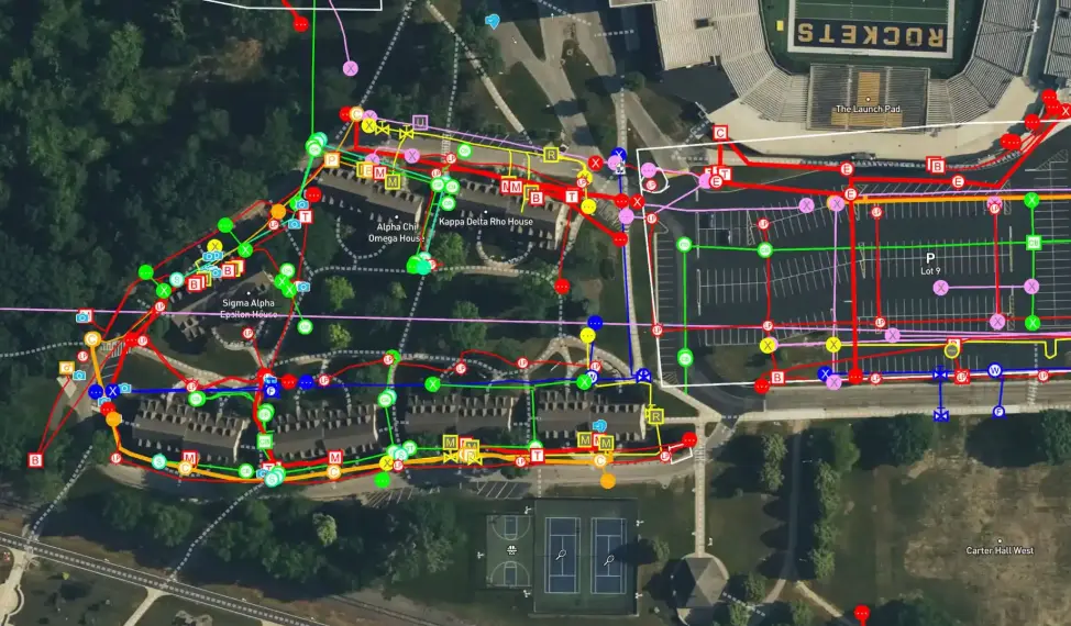
How GPRS Helps Protect San Francisco Bay Gas Stations From Subsurface Damage
From soda fountains to gas pumps, Rebekah Davies is responsible for ensuring a frictionless experience anytime you visit a BP gas station in the San Francisco Bay Area.
As a Site Maintenance Supervisor, Davies oversees every aspect of her stations’ operations outside of the employees.

“Anything that’s a capital expense, including plumbing, fuel dispensers, parking lots, the Veeder-Root which makes the tanks run,” she said. “And there are a couple little carve-outs beyond that: the fountain machines that get your soda, the registers that allow you transactions, the car washes. All of that is on me to maintain.”
It’s also Davies’ responsibility to ensure that when excavation occurs at or near one of her stations, it’s conducted safely. BP requires its sites to hire a professional utility locating company to map and mark out buried utilities, underground storage tanks (USTs) and any other subsurface obstructions prior to any excavations penetrating deeper than three inches into the earth.
“And just to make sure we’re covered, we [have] the whole site [marked],” Davies said.
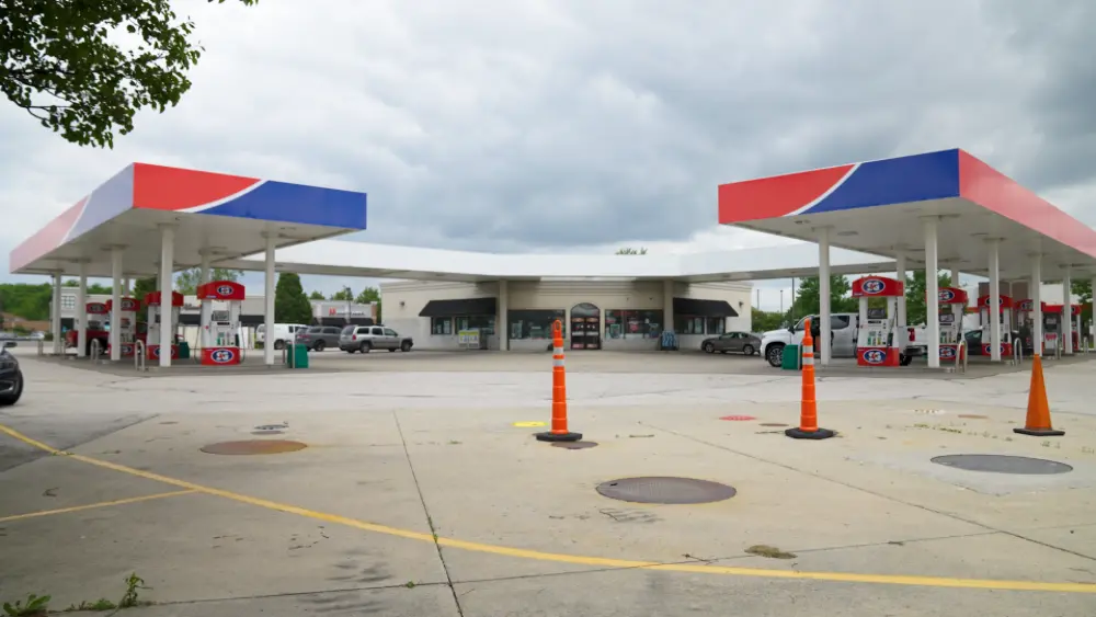
Striking a buried utility while excavating can have devastating consequences – and hitting something underneath a gas station can be even worse. While calling 811 is the first step you should always take to avoid subsurface damage when planning an excavation project, it’s important to remember that not every buried utility belongs to a provider registered with 811 – meaning they won’t know it’s there until you’ve hit it.
GPRS Utility Locating Services complement 811 by fully locating and mapping the buried infrastructure in your project area. Utilizing ground penetrating radar (GPR) and electromagnetic (EM) locating, our SIM-certified Project Managers have achieved and maintain a 99.8%+ rate of accuracy when locating buried utilities.
Davies said she relies exclusively on GPRS to provide utility locating services at her sites.
“The quality of the reports your team provides is always really good,” she said. “I have never had something where I thought ‘Wow, you guys really phoned that in. And the responsiveness – I don’t think it’s ever taken longer than an hour to get a response from somebody to get a job set up, and then it never takes more than a day or two to get the full, detailed report with the photos. There’s never been a point where I thought ‘Wow, I wish this was done better.’”
When you hire GPRS to locate buried utilities, we go above and beyond to ensure you have all the data you need to stay on time, on budget, and safe. This was evident recently when Davies contacted us to scan at one of her stations prior to the re-trenching of the property’s swale, a trench used to manage stormwater runoff and infiltration.
GPRS located utilities for the whole site and uploaded the data collected into SiteMap® (patent pending), our infrastructure mapping platform where Davies has 24/7, secure access to this critical information from any computer, tablet, or smartphone.
This came in handy later when the station was installing new bollards. Davies was able to use the data we’d previously collected to discover that a conduit ran directly beneath where they intended to install the protective structures.
“I was able to know, because you guys had already scanned the whole site, that the conduit we needed to avoid was directly beneath where those bollards needed to go,” Davies said. “So, I already had that information because your team did a really thorough job. Even though it was on the opposite side of the lot from what I was looking at, they chose to do it well and thoroughly and we had zero conflicts [during the bollard installation].”
Thanks to a stringent dig policy and the accurate, actionable data provided by GPRS, Davies says BP’s West Cost Team has had zero ground strikes during their excavation projects.
“Because your team does such a thorough job, I don’t need to be [on-site when utility locating occurs],” she said. “I don’t have to stand there, because I can use the information that I’m given in the report to find out what I need about where things are. So, I don’t need to stand there with [you].”
GPRS Intelligently Visualizes The Built World® to keep your projects on time, on budget, and safe.
What can we help you visualize?
Frequently Asked Questions
What does GPRS give me when I hire you to conduct a utility locate?
Our Project Managers flag and paint our findings directly on the surface. This method of communication is the most accurate form of marking when excavation is expected to commence within a few days of service.
GPRS also uses a global positioning system (GPS) to collect data points of findings. We use this data to generate a plan, KMZ file, satellite overlay, or CAD file to permanently preserve results for future use. GPRS does not provide land surveying services. If you need land surveying services, please contact a professional land surveyor.
Please contact us to discuss the pricing and marking options your project may require.
Can GPRS locate PVC piping and other non-conductive utilities?
GPR scanning is exceptionally effective at locating all types of subsurface materials. There are times when PVC pipes do not provide an adequate signal to ground penetrating radar equipment and can’t be properly located by traditional methods. However, GPRS Project Managers are expertly trained at multiple methods of utility locating.
Top Four Trends Reshaping Facilities Management
Facilities management (FM) is entering a new era of innovation and impact.
As companies place greater emphasis on sustainability, operational efficiency, and long-term resilience, the tools and strategies that support facilities management must evolve accordingly. Over the next five years, four transformative trends will redefine the facilities management landscape. GPRS stands ready as a trusted partner, empowering companies to navigate and lead this evolution with confidence.
These trends are unlocking new possibilities for how facilities are planned, maintained, and optimized. From digital integration to data-driven decision-making, the facilities management industry is profoundly shifting. Backed by cutting-edge technologies and a commitment to precision and reliability, GPRS is empowering facility teams to stay ahead of the curve and meet tomorrow’s challenges with confidence.
1. Sustainability and ESG Goals Are Shaping the Future of Facilities Management
Environmental, Social, and Governance (ESG) Goals are now essential in how facilities are planned, built, and managed. Companies must show progress in areas like cutting greenhouse gas emissions, reducing waste, using energy wisely, and protecting land.
Facility managers need to include sustainability in every stage of a building’s life – from design and construction to daily operations and upgrades. They also need accurate, current data to meet rules, earn green building certifications (like LEED), and plan for the future.
Sustainable facilities management means using better materials, limiting harm to the environment, and making sure upgrades support ESG goals. As more companies aim for net-zero emissions and climate readiness, facilities teams must be ready with tools and systems that support these goals without risking safety or performance.
2. Technology Integration: Turning Static Records into Smarter Tools
The facilities management industry is undergoing a profound digital transformation, driven by the adoption of technologies like Internet of Things (IoT), artificial intelligence (AI), and digital twins. These innovations empower teams to move beyond reactive maintenance, enabling predictive strategies, real-time system monitoring, and data-driven scenario planning that reduce risk and optimize performance.
IoT sensors embedded in building systems provide continuous insights into everything from HVAC efficiency to water consumption. AI-powered analytics interpret this data to detect anomalies and recommend proactive maintenance. Digital twins – virtual models of physical assets – offer facility managers an immersive way to visualize, simulate, and manage infrastructure. From energy modeling to emergency preparedness, these tools redefine how facilities are operated and maintained.
The success of these technologies, however, depends on the accuracy and completeness of the foundational data they rely on. Without a reliable understanding of existing conditions, even the most advanced digital tools can fall short; leading to misinformed decisions, operational inefficiencies, and missed opportunities.
That’s where SiteMap®(patent pending), powered by GPRS, becomes indispensable. As a cloud-based, interactive infrastructure mapping and facility management platform, SiteMap transforms outdated utility records into dynamic, visual data that integrates seamlessly into digital ecosystems. It serves as a single source of truth for both aboveground and subsurface infrastructure, fostering collaboration across departments and external partners. Whether deployed independently or as part of a broader digital twin strategy, SiteMap ensures that facilities teams have the accurate, accessible data they need to lead the next generation of facilities management.
3. Labor Shortages Require Smarter, Scalable Solutions
Staffing challenges are transforming how facilities teams operate. As the availability of skilled tradespeople declines and experienced professionals retire, many organizations are rethinking how they preserve institutional knowledge and maintain continuity.
This shift comes at a time when facilities are becoming more complex. Managing aging infrastructure, integrating advanced technologies, and staying compliant with evolving regulations require specialized expertise, yet the incoming workforce isn’t growing fast enough to meet demand.
To adapt, facilities teams are embracing smarter, more scalable tools that reduce dependence on individual expertise and make critical infrastructure data accessible to everyone. Intuitive software platforms, mobile-enabled systems, and visual data tools are helping teams better understand and manage complex environments with greater ease and efficiency.
By digitizing and centralizing facility data, organizations can capture and retain institutional knowledge – ensuring it’s readily available to new team members without relying on outdated paper records or informal handoffs. These tools can accelerate onboarding, standardize workflows, and enhance teamwork across departments and contractors.
In today’s evolving workforce landscape, access to accurate, comprehensible infrastructure data is no longer optional – it’s essential for maintaining productivity, safety, and long-term resilience.
4. Economic Pressures Demand Smarter Tools
Financial realities are reshaping how facilities are managed. As material costs rise, labor remains in short supply, and capital budgets tighten, facilities teams are challenged to deliver greater value with fewer resources. At the same time, leadership is placing increased focus on return on investment (ROI), operational efficiency, and sustainable cost control.
This evolving landscape encourages a more strategic approach to facilities management – one that emphasizes data-driven planning, proactive maintenance, and risk reduction. Whether it’s a renovation, system upgrade, or new construction, every project must be carefully planned and executed to ensure efficiency, avoid delays, and prevent unnecessary expenses.
Facilities managers are also being called upon to make investment decisions backed by clear, measurable data. Reliable infrastructure information is essential for accurate budgeting, forecasting, and performance tracking. Without it, companies risk the chance of running into unexpected costs such as utility strikes, change orders, or compliance issues that can impact both timelines and margins.
To meet these demands, companies are embracing technologies that enhance visibility, streamline operations, and reduce inefficiencies. With the right tools in place, teams can plan with confidence, stay on schedule, and make the most of every dollar invested.
How GPRS Supports the Future of Facilities Management
As facilities management becomes data-driven and complex, access to accurate, centralized infrastructure information is more important than ever. GPRS is meeting this need head-on – empowering facilities teams with the tools, technology, and expertise to manage above and belowground infrastructure with greater accuracy, accessibility, and efficiency.
GPRS supports the future of facilities management by delivering accurate infrastructure data, collected through specialized services like utility locating, concrete scanning, video pipe inspection, and 3D laser scanning. Every data point is verified in the field by our highly trained Project Managers and backed by our 99.8% accuracy rate. Because when it comes to safety and planning, precision matters. That commitment is further reinforced by our industry-exclusive Green Box Guarantee, which promises obstruction-free areas for cutting or coring because we stand behind the accuracy of our work. This level of confidence and accountability is what sets GPRS apart.
All verified data is then seamlessly integrated into SiteMap, where it’s organized, visualized, and continuously updated – giving teams the clarity they need to make informed decisions, reduce risk, and collaborate more effectively.
GPRS also plays a role in supporting Facility Condition Assessments (FCA) by delivering the accurate, field-verified infrastructure data teams need to evaluate asset health, plan upgrades, and maintain compliance with ESG and safety standards. Because every data point is collected by GPRS Project Managers using advanced technologies and backed by our 99.8% accuracy rate, facilities teams can trust the insights they rely on for long-term planning.
The Future of Facilities Management Starts with GPRS
The next five years will bring transformative change to facilities management. Sustainability goals, digital transformation, workforce shifts, and economic pressures will all influence how facilities are built, maintained, and optimized. To stay ahead, facility managers need tools that are powerful and purpose-built for the challenges they face.
GPRS is your partner. With industry-leading accuracy, advanced field services, and a commitment to complete infrastructure visibility, GPRS equips facilities teams to build smarter, safer, and more resilient environments.
What can we help you visualize?
FREQUENTLY ASKED QUESTIONS
What makes GPRS a trusted partner in modern facilities management?
GPRS stands out for our commitment to precision, safety, and innovation. With a 99.8% accuracy rate, GPRS ensures that facility teams have reliable data for planning and operations. Our Green Box Guarantee provides added confidence by promising obstruction-free areas for cutting or coring. This level of accountability helps organizations reduce risk, avoid costly errors, and maintain compliance with safety and ESG standards.
What services does GPRS provide to support facilities management teams?
GPRS offers a comprehensive suite of services designed to give facilities teams complete visibility into their infrastructure. These services include utility locating, concrete scanning, video pipe inspection, and 3D laser scanning. Each service is performed by highly trained Project Managers and backed by a 99.8% accuracy rate. This ensures that teams can plan upgrades, renovations, and maintenance with confidence – reducing risk, avoiding costly errors, and improving overall project outcomes.
How does SiteMap® support smarter infrastructure management?
SiteMap transforms outdated utility records into dynamic, visual data. It centralizes both aboveground and subsurface infrastructure information, making it accessible and actionable for facility teams. SiteMap enhances collaboration, supports predictive maintenance, and ensures that decisions are based on accurate, field-verified data.
How GPRS Pinpointed a Leak Blocking Employee Entrance at a Washington Manufacturing Facility
When a large, standing pool of water blocked employees from entering a manufacturing facility in Kent, Washington, it created a real headache. Employees had to use an alternate entrance that was further away from their normal entrance into the building.
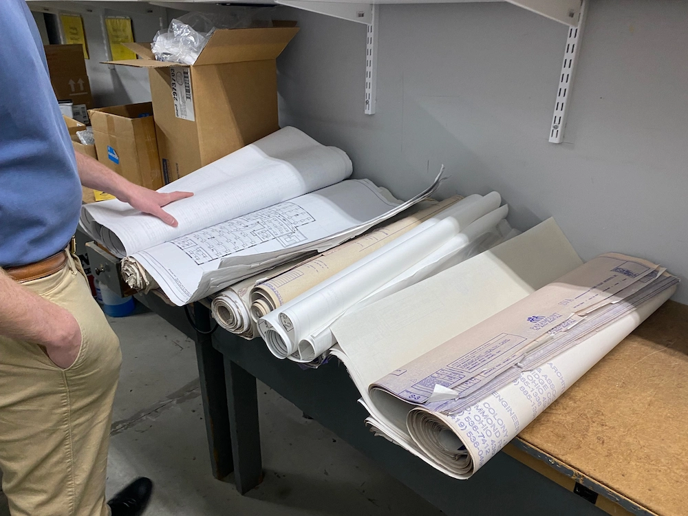
The source of the problem was obvious to the facility managers – a large water leak. Not only was that leak creating a nuisance for employees getting to work, it was costing the company money from the resulting non-revenue water loss. So, they did what any manager would do and checked the as-built records for their domestic water lines and fire loop to trace the source of the leak…
And that’s when they realized those as-builts were outdated and inaccurate.
To make matters worse, the business’ long-time facility manager had retired, taking all of his institutional knowledge with him. So, they hired a local leak detection contractor – two of them, actually – but both provided inaccurate information on the location of the leak.
The incorrect information from those attempted leak detection surveys led to unnecessary and costly concrete demolition and digging. The facility needed to find the leak, to stop losing money on water loss and restore employee access to the building.
So, they called GPRS for help.

GPRS Project Manager Derek Kauffman worked with the two facility managers to establish a plan to locate the suspected lines that were the source of the leak. Kauffman used electromagnetic (EM) locating and ground penetrating radar (GPR) scanning to locate the multiple water lines feeding the building. Once the lines were located, he planned to use acoustic leak detection equipment to pinpoint the leak.
“The facility manager showed me where the riser was in the building, which was close to where the water was coming up, so that gave me hope,” said Derek Kauffman.
What’s the difference between a domestic water system riser and a fire loop system riser?
A domestic water system riser, in this case, delivers potable (drinking) water to the building for uses such as sinks, toilets, showers, and other “domestic” uses. A fire loop riser delivers water specifically for the fire suppression system, and is independent of the domestic water system.
The GPRS team used an electromagnetic locator paired with GPR to accurately map the fire loop and domestic water lines. This precision locating helped clarify that the suspected fire riser was, in fact, a domestic water line.
To pinpoint the leak, Kauffman employed acoustic leak detection technology on the domestic water riser. Clear indications of a leak were detected, allowing GPRS to provide the client with an exact location.
“My investigation kept leading me to the riser, which made me think the leak was at the 90-degree leading up into the building. I put my microphone on that riser and it about blew my eardrums out,” Kauffman explained.

Because Kauffman started the project by locating all the possible water lines leading to the building and didn’t rely on previous site information, he was able to get a complete picture of the potential locations of the leak.
“I did the whole [area] locate, and it was difficult, but I wanted to give them more information about their water system. They told me I nailed it” said Kauffman.
Since the client was leery of more unnecessary digging after their previous potholing on the other leak detection companies’ data had failed, Kauffman offered to scan the concrete above the line location, so the client could core-drill and confirm the water line was there. The client readily agreed.
The client used the location information from GPRS to pothole and expose the leak at the 90-degree fitting where the pipe enters the building — precisely where GPRS had indicated.
Thanks to GPRS’s accurate mapping of the water system, and locating the precise area of the leak, the client avoided further unnecessary digging and costly repairs. The leak was fixed, restoring normal employee access and preventing continued water loss.
EPA Statistics and Facts: Why Are Annual Water Loss Surveys Important?
GPRS combines leading-edge technology with experienced field expertise to deliver fast, reliable solutions — saving clients time, money, and most importantly, keeping jobsites safer.
Whether you need help locating water leaks, mapping underground utilities, or resolving complex infrastructure issues, GPRS Intelligently Visualizes The Built World® to keep your projects on time, on budget, and safe.
What can we help you visualize?
The Power of Photogrammetry
Photogrammetry has become an essential reality capture tool in the architecture, engineering, construction, and facilities management industries, offering the ability to convert photographs into accurate 2D floor plans, 3D models, and immersive virtual tours.
By capturing buildings and infrastructure and translating them into digital assets, photogrammetry supports a wide range of workflows, from planning and design to execution and long-term maintenance.

Why Documentation Matters
Accurate documentation is critical at every stage of a construction project.
Architects and engineers use reality capture photogrammetry during the design phase to ensure their plans align with existing building conditions. General contractors rely on it for pre-construction planning and to verify progress at key milestones, helping to ensure the project stays on track and meets specifications.
Once construction is complete, facility managers depend on this data to locate critical systems and streamline maintenance, saving time and reducing operational costs.
CAD and BIM Creation with Photogrammetry
Photogrammetry enables architecture, engineering, and construction (AEC) professionals to rapidly convert buildings and infrastructure into precise digital assets.
Through scan-to-BIM workflows, high-resolution images are transformed into 2D floor plans and 3D models that integrate seamlessly with CAD software and BIM platforms like Autodesk Revit. This technology accelerates as-built documentation, reduces manual modeling, improves accuracy, and enhances collaboration across project teams.

What Can Be Created with Photogrammetry Data?
2D Floor Plans
Scaled representations of a building’s layout, showing walls, doors, windows, and room dimensions. 2D floors plans are ideal for planning, renovations, real estate, and emergency response.
3D Models
Using formats like E57, photogrammetry produces detailed digital twins compatible with Autodesk Revit, AutoCAD, and Navisworks. These 3D models support virtual design, material estimation, post-construction documentation, and facility management.
Virtual Tour
Capturing 134.2 MP panoramic HDR images, photogrammetry enables interactive, navigable 3D virtual tours. These are commonly used in real estate, construction progress tracking, and facility management.
Point Cloud
With up to 1.5 million points per scan, photogrammetry generates dense 3D point clouds that capture the exact shape and surface of architectural, structural, and MEP elements, forming the foundation for accurate CAD and BIM modeling.
2D Photography
4K high-resolution images captured during the photogrammetric process can be used for visual documentation, inspection, and reference throughout a project’s lifecycle.
What are the Advantages of Photogrammetry Scan-to-BIM Workflows?
Faster Capture of As-Built Conditions
Rapid photogrammetry scanning, often completed in seconds, outpaces traditional LiDAR methods.
Seamless Integration with Design Software
Easily import photogrammetry data into Autodesk Revit and other BIM platforms.
Automated Model Generation
Generate LOD 200 BIM-ready files in IFC or RVT formats, reducing manual work.
Improved Collaboration and Accessibility
Share digital twins for real-time stakeholder collaboration.
Reduced Errors and Rework
High-accuracy scans reduce costly rework by identifying issues, such as electrical or plumbing conflicts, before they become hidden behind drywall.
Swinerton Keeps Construction Moving Forward with Digital Twins
Swinerton, a leading construction firm, leveraged digital twin technology to keep projects on track. By using photogrammetry to create immersive 3D walkthroughs of job sites, Swinerton eliminated the need for in-person visits, reduced client travel by 100%, and reduced architect and MEP travel by 50%. This approach not only saved time and costs but also prevented project delays and rework. The digital twins enabled real-time collaboration, precise measurements, and streamlined issue resolution, helping Swinerton shave weeks off project timelines and enhance communication across teams.

What Industries Use Photogrammetry?
Photogrammetry is transforming the architecture, engineering, and construction industry by making reality data capture faster, more accurate, and more accessible. From planning and design to execution and maintenance, its applications are vast and impactful.
Construction
Used to capture detailed site and building imagery data for accurate planning, visualization, and documentation.
Civil Engineering
Supports the design of roads, bridges, airports, and utilities through terrain mapping and infrastructure modeling.
Structural Engineering
Provides precise models for assessing building integrity, planning reinforcements, and designing new structures.
Cultural Heritage & Preservation
Digitally documents historical sites and artifacts for assessment, restoration, research, and virtual tourism.
Real Estate
Enhances listings with virtual tours, floor plans, and high-resolution imagery to attract buyers and renters.
Industrial & Facility Management
Aids in asset documentation, space optimization, and maintenance planning for facilities and plants.
Case Study: Hotel Renovation Design Planning with 3D Photogrammetry
GPRS used 3D photogrammetry to capture over 600,000 square feet of interior space across four hotel properties in Dayton and Cleveland, Ohio. The client needed accurate 2D floor plans of guest rooms, common areas, meeting spaces, and offices to support renovation planning, without disrupting hotel operations or reducing guest occupancy.
The non-intrusive photogrammetry scanning process delivered precise as-built documentation in a single mobilization for each hotel, eliminating the need for return site visits. This efficient approach provided the design team with comprehensive spatial data while preserving the guest experience and streamlining project timelines.
"The scans were great. I’m a believer. We couldn’t have done this project without it. We will never do a renovation again without a scan so we will be calling you." - Chuck T.

Can GPRS Provide Photogrammetry Services?
Yes. GPRS Photogrammetry Services provide customers the opportunity to better manage design, construction, and operations with a digital record of their space. All architectural, structural, and MEP system details, plus utility locates and concrete markings can be documented with 20-millimeter accuracy.
3D photogrammetry delivers GPRS’ clients precise spatial data for planning, analysis, and calculations. Clients can extract geometric information from the two-dimensional images. Overlapping photographs can be rectified to create digital twins, 2D floor plans, virtual tours, 3D models, LiDAR point clouds, topographical maps, and more. This precise data aids in project planning, execution, and ongoing maintenance.
Read more about photogrammetry.
For more information, contact us today at 419-843-7226 or email laser@gprsinc.com.
What can we help you visualize?
Frequently Asked Questions?
How does 3D photogrammetry work?
Photogrammetry uses overlapping images captured from different angles to create precise digital twins, 2D floor plans, virtual tours, 3D models, LiDAR point clouds, topographical maps, and more. Specialized software analyzes the photos, identifies common points, and reconstructs depth, shape, and texture.
What is the Meaning of Photogrammetry?
When you break down the word photogrammetry – “photo” refers to light, “gram” means drawing, and “metry” refers to measurements. Photogrammetry uses photos to gather measurements from which drawings, maps, and models can be created.
What is the Science Behind Photogrammetry?
Triangulation is the principle used by photogrammetry to produce three-dimensional coordinates. By mathematically intersecting converging lines in space, the precise location of a point can be determined.
What is the Difference Between Photogrammetry and LiDAR?
Photogrammetry and LiDAR are both remote sensing reality capture techniques used to create as-builts, but they differ significantly in how they capture data and the resulting accuracy. Photogrammetry uses photographs to derive measurements, while LiDAR uses lasers to directly measure distances.
How GPRS VPI Services Kept a Train Platform Rehab Project on Track
GPRS’ sewer inspection services helped a train platform rehabilitation project in Norman, Oklahoma stay on track.
GPRS Project Manager Joe Meyer was tasked with inspecting storm sewer laterals and the mainline, all of which ran parallel to active train tracks. Each sewer lateral - pipes that carry stormwater from a home or business to the public main - ranged from 15 to 20 feet in length, while the mainline was approximately 350 feet long.
The client’s current as-builts indicated there were five sewer laterals connected to the mainline. They needed the precise location, and videos documenting the condition of each of these existing pipes to help them tie the lines into new roof drains.
Meyer utilized the ROVVER X SAT II Lateral Launch Camera to inspect the sewer lines and mainline. GPRS VPI Project Managers also use the ROVVER X SAT II for pre & post lateral installation inspections and cross bore inspections, which you can learn more about here.
All GPRS Project Managers are NASSCO (National Association of Sewer Service Companies) certified in pipeline (PACP), lateral (LACP), and manhole (MACP) assessments. GPRS NASSCO reports offer interactive insight into any defects found, with photographs and video of each pipe segment and the identified issues. Any defects found are ranked by severity, so you know what needs addressing first and exactly where you need to dig to complete your repairs.

Meyer’s investigation revealed a discrepancy between the client’s existing as-built documents and what was buried in the ground.
“They had listed 5 laterals and one mainline [on their current plans], but in reality, there was only four laterals and one mainline,” he explained.
Of bigger concern was what Meyer found in those four laterals.
“The mainline ran fine. I found all the features, everything was great,” he said. “The only problem was - and this was helpful for them - that all four laterals that were going to an underground pipe were blocked.”
Without the data Meyer collected, the client would have likely encountered serious sewer backups after completing their rehab project.
“They would have probably installed those new roof drains just to have them all back up because they did not know that those were all blocked,” Meyer explained. “That was the key piece of information that, while it was not good news, it was news that prevented them from going on and putting sod down and doing all this and then tearing it all back up just to fix it again.”
By identifying the blockages with his sewer inspection equipment, Meyer saved the client from the costly, and risky, large-scale excavation that would have likely needed to have occurred if the defects hadn’t been identified until after construction was completed.
And since the work was happening right along an active rail line, the information Meyer presented was especially important as the slightest disturbance to the soil could compromise the tracks and make it dangerous for trains to travel through the area.
“Excavation around rail systems requires a lot of permitting and can shut things down for quite some time,” Meyer said. “With the information I was able to give them, they could do targeted excavations, maybe even use hydrovac instead of having to get an excavator out there to do major dirt work.”
Once the client has cleared the blockages from the laterals, Meyer will return to complete his mapping of the storm system.
The data Meyer collected and will collect in the future will be at the client’s fingertips throughout the project lifecycle thank to SiteMap® (patent pending), GPRS’ cloud-based infrastructure management platform. With SiteMap, the client can reference their data 24/7 during every step of the renovation process. And it can be securely shared with members of the project team to ensure seamless communication and collaboration.
“The superintendent was most interested in those plot points on SiteMap so that they could perform targeted excavation, which was important to them because of the lines’ proximity to the rail system,” Meyer explained.
From skyscrapers to sewer lines, GPRS Intelligently Visualizes The Built World® to keep your projects on time, on budget, and safe.
What can we help you visualize?
FREQUENTLY ASKED QUESTIONS
What size sewer and storm pipes can GPRS inspect?
Our elite, NASSCO-certified VPI Project Managers have the capabilities to inspect pipes from 2” in diameter and up.
What deliverables does GPRS offer when conducting a sewer pipe inspection?
GPRS is proud to offer WinCan reporting to our Video Pipe Inspection clients. Maintaining sewers starts with understanding sewer condition, and WinCan allows GPRS Project Managers to collect detailed, NASSCO-compliant inspection data. GPRS Project Managers not only inspect the interior condition of sewer pipes, laterals, and manholes – they can also provide a map of their location. The GPRS Mapping & Modeling Department can provide detailed GPS overlays and CAD files. Our detailed WinCan/NASSCO reports contain screenshots of the interior condition of the pipe segments that we inspect, as well as a video file for further evaluation, documentation, and/or reference.
From D- to D+: The Slow Climb of U.S. Transit and Stormwater Systems
Transit and stormwater once again found themselves at the bottom of the grading scale in the 2025 American Society of Civil Engineers (ASCE) Infrastructure Report Card.
The two sectors each earned a D+ grade. While this represents a modest improvement from previous years, where grades hovered at D or D-, the reality remains stark: these critical systems are underfunded, outdated, and increasingly vulnerable to the pressures of climate change and urban growth.
Why Transit and Stormwater Matter
Transit and stormwater systems are the unsung heroes of modern infrastructure. Public transit connects millions of Americans to jobs, education, and healthcare, while stormwater systems protect communities from flooding, water pollution, and infrastructure damage.
Both systems, however, have long suffered from chronic neglect.
The ASCE’s 2025 report underscores this neglect, noting that while some progress has been made, the pace of improvement is far too slow to meet the demands of a growing and changing nation.

Transit: A System Stuck in the Past
Aging Infrastructure, Declining Ridership
America’s public transit systems – buses, subways, light rail, and commuter trains – are aging rapidly. Many systems, particularly in older cities like New York, Boston, and Philadelphia, rely on infrastructure that dates to the early 20th century. Deferred maintenance has led to frequent service disruptions, safety concerns, and declining reliability.
The COVID-19 pandemic dealt a further blow to transit systems, with ridership plummeting and fare revenues drying up. While ridership has rebounded somewhat in 2024 and 2025, it remains below pre-pandemic levels in many cities. This has left transit agencies struggling to balance budgets while maintaining service levels.

Funding Gaps and Political Hurdles
The ASCE estimates that the U.S. faces a $176 billion transit investment gap through 2039. While the Infrastructure Investment and Jobs Act (IIJA) of 2021 provided a historic $39 billion for public transit, experts argue that this is only a down payment on what’s truly needed.
Political will remains a major barrier. Transit funding often becomes a partisan issue, with urban systems receiving less support in federal and state legislatures dominated by rural interests. Moreover, the fragmented nature of transit governance – spread across thousands of local agencies – makes coordinated investment and planning difficult.

Stormwater: The Hidden Crisis Beneath Our Feet
Outdated Systems, Growing Threats
Stormwater infrastructure – culverts, drains, retention basins, and green infrastructure – is often invisible until it fails. And failures are becoming more common. As climate change drives more frequent and intense storms, aging stormwater systems are being overwhelmed, leading to flash floods, sewer overflows, and water contamination.
Many stormwater systems in the U.S. were designed decades ago, based on outdated rainfall models. In cities with combined sewer systems, heavy rains can cause raw sewage to overflow into rivers and streets. The ASCE notes that more than 850 billion gallons of untreated sewage are discharged annually due to combined sewer overflows.
Underinvestment and Lack of Standards
Unlike drinking water and wastewater systems, stormwater infrastructure has historically lacked dedicated funding streams. It’s often funded piecemeal through local taxes or general funds, making long-term planning difficult. The ASCE estimates a $134 billion investment gap in stormwater infrastructure over the next 20 years.
There is also no national standard for stormwater system performance, leading to wide disparities in quality and resilience. Some cities, like Philadelphia and Portland, have pioneered green infrastructure solutions – such as permeable pavements and rain gardens – but these remain the exception rather than the rule.
Signs of Progress – and Hope
Despite the grim grades, there are glimmers of progress. The IIJA included $55 billion for water infrastructure, some of which is earmarked for stormwater improvements. The Environmental Protection Agency (EPA) has also expanded its Clean Water State Revolving Fund, providing low-interest loans for stormwater projects.
In the transit sector, cities like Los Angeles, Seattle, and Washington, D.C. are investing heavily in new rail lines, electric buses, and smart fare systems. These projects not only modernize infrastructure but also reduce greenhouse gas emissions and improve air quality.
Public awareness is also growing. As extreme weather events become more common, voters and policymakers are beginning to recognize the importance of resilient infrastructure. In 2024, several states passed bond measures to fund stormwater upgrades and transit expansions.
What Needs to Happen Next
Bold, coordinated action is needed to significantly improve the country’s transit and stormwater systems.
1. Increase and Sustain Federal Investment
Short-term funding boosts are not enough. Long-term, predictable funding for both transit and stormwater systems, with a focus on equity and climate resilience, is vital to improving these critical systems to handle modern society’s requirements.
2. Modernize Design Standards
Infrastructure must be built for the climate of the future, not the past. This means updating rainfall models, incorporating green infrastructure, and designing transit systems that are accessible, efficient, and low emission.
3. Engage the Public
Public support is crucial. Outreach campaigns that highlight the benefits of transit and stormwater investments – such as cleaner water, reduced flooding, and better mobility – can build political momentum.
GPRS offers a comprehensive suite of subsurface damage prevention, existing conditions documentation, and construction & facilities project management services designed to help keep infrastructure improvement projects on time, on budget, and safe.
We utilize state-of-the-art technology such as ground penetrating radar (GPR) scanners, electromagnetic (EM) locators, 3D laser scanners, and remote-controlled video pipe inspection crawlers to ensure the integrity of your buried infrastructure and help you avoid subsurface damage when breaking ground. Our in-house Mapping & Modeling Team can visualize the field-verified, accurate data collected by our SIM and NASSCO-certified Project Managers to suit your planning, and operations & maintenance (O&M) needs.
All this information is at you and your team’s fingertips 24/7, accessible via any computer, tablet or smartphone thanks to SiteMap® (patent pending), our project & facility management application that provides accurate existing conditions documentation to protect your assets and people.
What can we help you visualize?
Frequently Asked Questions
What type of informational output is provided when GPRS conducts a utility locate?
Our Project Managers flag and paint our findings directly on the surface. This method of communication is the most accurate form of marking when excavation is expected to commence within a few days of service.
GPRS also uses a global positioning system (GPS) to collect data points of findings. We use this data to generate a plan, KMZ file, satellite overlay, or CAD file to permanently preserve results for future use. GPRS does not provide land surveying services. If you need land surveying services, please contact a professional land surveyor. Please contact us to discuss the pricing and marking options your project may require.
What types of concrete scanning does GPRS offer?
GPRS provides two specific but different scanning services: elevated concrete slab scanning and concrete slab-on-grade locating. Elevated concrete slab scanning involves detecting embedded electrical conduits, rebar, post-tension cables, and more before core drilling a hole through the slab. Performing a concrete slab-on-grade locating service typically involves scanning a trench line for conduits before conducting saw cutting and trenching to install a sanitary pipe, water line, or something similar.
Why Ground Penetrating Radar Remains the Gold Standard for Non-Destructive Utility Locating and Concrete Scanning
It’s been decades since ground penetrating radar (GPR) established itself as the preeminent tool for utility locating and precision concrete imaging.
And despite the emergence of alternative technologies, GPR continues to be the best option for nondestructive subsurface investigation and utility surveying.
What Is Ground Penetrating Radar?
GPR is a geophysical method that uses radar pulses to image the subsurface. It works by transmitting high-frequency radio waves into the ground or a structure. When these waves encounter a material with different dielectric properties, they reflect back to the surface, where they are captured by a receiver. The data is then processed to create a visual representation of the subsurface features. The interactions between the radio waves and buried objects are illustrated as hyperbolas that vary in size and shape depending on the material that was located.

Key Advantages of GPR
Non-Destructive and Non-Invasive
One of the most significant benefits of GPR is that it allows for thorough subsurface investigation without any physical disruption. Unlike traditional methods that may require drilling or excavation, GPR preserves the integrity of the site. This is particularly important in urban environments, historical sites, or active facilities where disruption must be minimized.
High Resolution and Accuracy
GPR provides high-resolution images that allow for precise identification and mapping of subsurface features. In concrete scanning, for example, GPR can detect rebar, post tension cables, conduits, and more with remarkable accuracy. This level of detail is critical for ensuring safety and avoiding costly mistakes during construction or renovation.
Versatility Across Materials and Environments
GPR is effective in a wide range of materials, including soil, rock, concrete, asphalt, and ice. It can be used in diverse environments – from highways and bridges to buildings and archaeological sites. Its adaptability makes it a go-to solution for utility locating, structural analysis, environmental assessment, and more.
Real-Time Results
Another major advantage of GPR is its ability to deliver real-time data. Properly trained GPR technicians like GPRS’ SIM-certified Project Managers can interpret findings on-site, enabling immediate decision-making. This is especially useful in fast-paced construction projects where delays can be costly.
Safety and Risk Mitigation
By accurately identifying the location of utilities and structural elements, GPR significantly reduces the risk of accidental strikes, which can lead to injuries, service disruptions, and legal liabilities. It also helps ensure compliance with safety regulations and industry standards.

Applications of GPR in Utility Locating and Concrete Scanning
Utility Locating
Before any excavation or trenching work, it's essential to know what lies beneath the surface. GPR can detect:
- Metallic and non-metallic pipes
- Electrical and communication conduits
- Water and sewer lines
- Underground storage tanks
Unlike electromagnetic (EM) locating, which only detects conductive materials, GPR can identify both metallic and non-metallic utilities, making it a more comprehensive solution.
Ideally, GPR and EM locating are used to complement each tool’s strengths and compensate for the other’s shortcomings.
Concrete Scanning
In concrete structures, GPR is used to:
- Locate rebar and post tension cables
- Identify embedded conduits and pipes
- Detect potential voids
- Measure slab thickness
This information is crucial for safe drilling, coring, and cutting operations, as well as for structural assessments and retrofitting projects.

Comparison with Alternative Technologies
While other technologies such as EM locating, ultrasonic testing, and X-ray imaging can help you visualize what’s below ground or within a concrete slab, none offer the same combination of benefits as GPR.
Electromagnetic Locators
Limited to conductive materials and often require access to both ends of a utility.
Ultrasound
Effective for certain structural assessments but lacks the depth and versatility of GPR.
X-ray Imaging
Provides high-resolution images but involves the use of potentially dangerous radioactive material, requires access to both sides of a structure, and is more expensive and time-consuming.
GPR, by contrast, is safe, fast, and capable of detecting a wide range of materials in various conditions.
Technological Advancements in GPR
Recent innovations have further solidified GPR’s position as the industry leader.
3D Imaging
Advanced software now allows for three-dimensional visualization of subsurface features, enhancing interpretation and reporting.
Wireless and Portable Systems
Modern GPR units are more compact and user-friendly, making them ideal for fieldwork in tight or remote locations.
Environmental and Economic Benefits
GPR also contributes to sustainability and cost-efficiency:
Reduces Waste
By preventing unnecessary excavation or demolition, GPR minimizes material waste.
Lowers Costs
Avoiding utility strikes and structural damage saves money on repairs, project delays, and liability claims.
Supports Green Building
Non-destructive testing (NDT) aligns with sustainable construction practices by preserving existing structures and reducing environmental impact.
Limitations and Considerations
While GPR is highly effective, it does have limitations. Its performance can be affected by:
- Soil Conditions: High clay content or saturated soils can attenuate radar signals
- Depth Penetration: GPR’s effective depth limit varies depending on the frequency of the GPR antenna being used and the material you’re attempting to locate
- Operator Skill: Accurate interpretation requires training and experience, which is why you should always hire a professional utility locating/concrete scanning company like GPRS rather than buying or renting a GPR unit and attempting the investigation yourself.
GPRS offers 99.8%+ accurate utility locating and concrete scanning services, utilizing GPR and other, complementary technologies to Intelligently Visualize The Built World® and keep your projects on time, on budget, and safe.
What can we help you visualize?
Frequently Asked Questions
Can GPR locate unmarked grave sites?
Yes, GPR can be used to determine the location of unmarked graves for site planning purposes. We can locate most grave sites, even those that have experienced material decomposition.
Can GPR scanners be used on CMU walls?
We can use GPR scanners on concrete masonry unit (CMU) walls and structures. GPR can also determine the presence or absence of grout, bond beams, vertical rebar, horizontal rebar, and joint reinforcing within the CMU structure.
GPRS Scans Over Four Acres of Crowded Utilities to Help a Large Plant Avoid Utility Strikes During a Sitewide Project
GPRS Project Manager Aaron Bradley followed the guidelines of Subsurface Investigation Methodology (SIM) to help a large plant safely install electrical conduit and avoid utility strikes.

The client had plans to add new electrical conduit across their facility. The areas that the client planned to add the utilities covered a vast majority of the plant and totaled over four acres of land. Because Bradley had worked with this client before, they felt comfortable trusting GPRS with such a large and important project.
“I've done a couple of smaller locates there. Then they decided to do this huge locate and because there's going to be such a large section of it completed, they decided to go with us,” Bradley said.
The client had no current or accurate as-built records of their underground utilities, so they would have been digging blind or doing lots of unnecessary potholing without the results Bradley gathered.
Bradley used both ground penetrating radar (GPR) and electromagnetic (EM) locators to scan, document, and assess the utilities located in the requested areas. Bradley’s use of multiple complementary technologies follows directly along with one of the three main teachings of Subsurface Investigation Methodology (SIM), the backbone of GPRS’ continuous 99.8% accuracy as a national utility locating company.
Subsurface Investigation Methodology is a standard operating procedure and set of professional specifications that work as a guide for utility locating experts when scanning for buried utility lines. All GPRS Project Managers are required to achieve SIM 101 certification, which requires 80 hours of hands-on training in a classroom setting and 320 hours of mentorship in the field. For reference, the American Society for Nondestructive Testing’s (ASNT) minimum training recommendation includes eight hours for training and 60 hours practicing GPR to achieve NDT Level 1 certification in ground penetrating radar (GPR) scanning.
SIM requires the use of multiple, complementary technologies, like GPR scanning and EM locating, when locating buried utilities or scanning a concrete slab.

While this wasn’t the largest scan Bradley had ever performed, he was surprised at the volume and density of underground utilities at the facility.
“There were so many electrical lines and random gas lines, that you wouldn't expect,” Bradley explained. “[The site also had] unknown pipes that hook up to it in one building and it somehow shoots all the way across the scan area going who knows where. There was just a lot of stuff going in every which way direction.”
Bradley marked out each utility using spray paint and flags. Once the scans were completed, the utility map was uploaded and securely sent to the client via SiteMap® (patent pending), GPRS’ digital infrastructure mapping software. With SiteMap, the field-verified and RTK positioned data is always at their fingertips allowing them to reference the results at every step of the project. Their utility map can even be in the palm of their hand on their mobile devices or tablets by using the SiteMap mobile app.
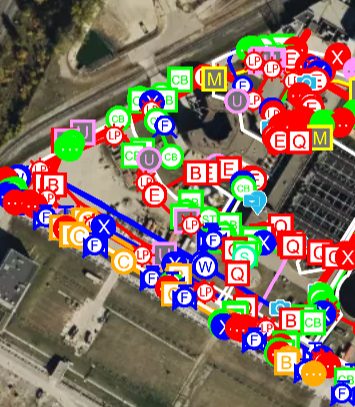
Due to the number of utilities in these areas, without GPRS’ 99.8% accurate scans and SiteMap, the chances of a utility strike would have been very high. Such a strike could have completely derailed the project.
The client communicated to Bradley their satisfaction with the results and data he presented.
“They were definitely happy with me because I got everything done and it all got to them when they needed it,” Bradley explained.
Following the initial scans of the area, Bradley has continued to help with this project.
“[The site contact and I] talk pretty regularly about the job,” Bradley said. “I've gone back there a few extra times just to re-mark some areas because it's so massive, they're doing all this demo, and the marks go away once they tear up the ground.”
While SiteMap retains all GPRS’ geolocated data, GPRS highly recommends having our Project Managers verify utility locations before digging. Potential soil shifts and increases in trenchless technology utility installations mean that every precaution should be taken before breaking ground.
The Purpose of Utility Locating and Mapping
Based on the Common Ground Alliance’s (CGA) DIRT Report, as much as 94% of reported utility strikes are attributed to inaccurate or missing utility location data and they have seen little movement in those figures in the last five years. Because of this, utility maps are very important.
The purpose of a utility map is to provide a comprehensive record of the subsurface infrastructure of a facility or any property, so any necessary excavation can be completed safely and maintenance or repairs can be planned more efficiently. GPRS highly recommends utility mapping as part of a general contractor or excavator’s ground disturbance policy. In fact, we offer complimentary dig policy reviews based on Subsurface Investigation Methodology.
There are four steps you should take to make sure you’ve properly assessed a job site before digging:
- Call your local 811 service
- Hire a Professional Private Utility Locator
- Update your Ground Disturbance Policy to Require Public & Private Utility Locating Before Excavation
- Utilize a Secure, Sharable Underground Utility Mapping Platform
GPRS is in pursuit of 100% subsurface damage prevention. With 99.8% accurate scans, SIM-certified Project Managers, and SiteMap, clients can dig with confidence knowing the chance of a utility strike has significantly reduced.
Whether your project is four acres or forty stories, GPRS Intelligently Visualizes the Built World® to keep your projects on time, on budget and safe.
What can we help you visualize?
FREQUENTLY ASKED QUESTIONS
Can GPRS Project Managers distinguish between the different utilities they locate?
In most situations, we can identify the utility in question without any problems, although it is not always possible to determine what type of utility is present. When this happens, we attempt to trace the utility to a valve, meter, control box, or other signifying markers to determine the type of utility buried.
How does SiteMap® assist with Utility Mapping?
SiteMap, powered by GPRS, is the industry-leading infrastructure management program. It is a single source of truth, housing the 99.8%+ accurate utility locating, concrete scanning, video pipe inspection, leak detection, and 3D laser scanning data our Project Managers collect on your job site. And the best part is you get a complimentary SiteMap Personal access when GPRS performs a utility locate for you.
How Do Commercial Real Estate Professionals Utilize 3D Laser Scanning Technology?
In commercial real estate, access to accurate, comprehensive site data is essential for making informed decisions across every phase of a property’s lifecycle. From acquisition and valuation to design, construction, and long-term management, 3D laser scanning provides real estate professionals with precise, millimeter-level insights that enhance efficiency and reduce risk. This reality capture technology transforms how properties are documented, analyzed, marketed, and maintained, empowering commercial real estate professionals to work smarter, faster, and with greater confidence.
What is 3D Laser Scanning?
3D laser scanning captures high-resolution spatial data by emitting LiDAR laser beams to measure distances with extreme precision. This process generates precise digital representations of physical spaces or objects, known as point clouds, that represent the scanned area in three dimensions. Point clouds can be processed into detailed 2D drawings, 3D models, virtual tours, and more, providing an accurate, real-world representation of a building or site.
3D laser scanning delivers comprehensive as-built site data with speed, accuracy, and no physical contact to aid the evaluation, design, construction, and facility management of commercial real estate projects.
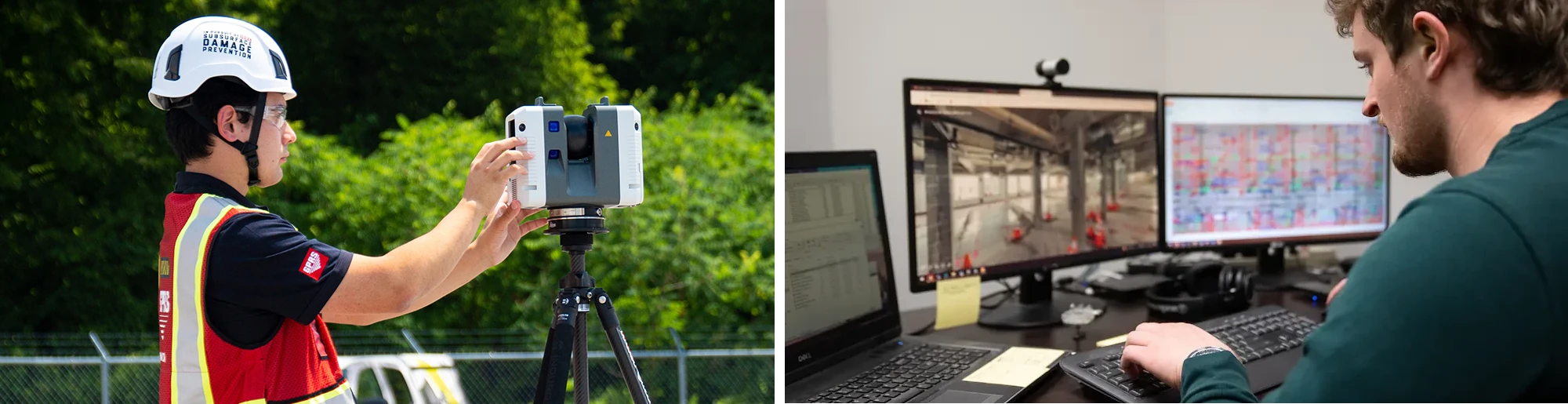
How Do CRE Professionals Utilize 3D Laser Scanning?
CRE professionals are utilizing 3D laser scanning technology in these aspects of a property’s lifecycle.
Property Documentation
- Capture architectural, structural, and MEP features with millimeter-level precision for accurate records
- Permanently document underground utilities, power, water, and telecom systems to support safe planning and construction
- Convert scan data into utility maps, 2D CAD drawings, and 3D BIM models for comprehensive building documentation
- Apply BOMA standards to measure areas within a building, including gross building area, usable area, and rentable area to calculate rentable square footage
Example: 3D laser scanning services captured every inch of a roughly 219,000-square-foot soft drink production facility, so that a digital twin of the space could be created to enable safe and efficient operations and maintenance. Read more about this project.

Property Valuation
- Receive accurate as-built data to support environmental assessments, zoning compliance, and structural evaluations before acquisition
- Utilize accurate square footage to determine property value, calculate rental rates, and assess usable vs. rentable space
- Allow investors to assess property conditions, revealing structural issues, cracks, and misalignment to identify and budget for repairs or maintenance
- Create a detailed visual and dimensional record of the property for buyers and sellers, insurance underwriting, and risk assessment
Example: A real estate investment firm used 3D laser scanning to capture accurate as-built data of a 200,000 sq ft industrial facility before acquisition. This data supports environmental assessments and zoning compliance, and helps appraisers determine the true market value based on usable square footage and structural integrity.

Lease Area Analysis
- Provide highly accurate measurements to verify rentable square footage, resolve discrepancies, and ensure BOMA compliance, streamlining lease negotiations
- Visualize and validate shared or common areas, such as lobbies, corridors, and amenity spaces, by clearly distinguishing between rentable and non-rentable square footage
Example: A property management company verified rentable square footage in a downtown office tower using BOMA-compliant laser scans. This resolved a dispute with a tenant over common area allocations and ensures lease terms reflect accurate rentable vs. usable space.

Marketing
- Present precise site layouts, floor plans, dimensions, and BOMA calculations to help tenants and buyers understand key property details
- Create immersive 3D models and 3D virtual tours that let tenants explore properties remotely, expanding reach and accelerating leasing
- Enhance listings with high-resolution images, 2D floor plans, and 3D virtual tours to showcase layout and flow
Example: A brokerage firm marketed a new mixed-use development by creating immersive 3D virtual tours and high-resolution floor plans. Prospective tenants can explore retail and office spaces remotely, accelerating leasing decisions and expanding reach to out-of-state clients.

Property Management
- Standardize documentation across multiple properties for consistent asset tracking and strategic planning
- Generate finish drawings to help building owners and facility managers understand layouts, systems, and equipment locations
- Use 3D scans as the foundation for a digital twin to support ongoing operations and maintenance
Example: 3D laser scanning services were performed for a 10-story office building, capturing existing above-ceiling interstitial HVAC systems on each floor, as well as mechanical rooms, chiller rooms, air handling unit rooms, and a basement tunnel connecting the utility area to the office building. Over 240,000 square foot of space was laser scanned to document the as-is conditions. The client was upgrading the HVAC system and GPRS developed a 3D model to aid the design process and reduce clashes. Read more about this project.

Space Planning & Optimization
- Enable developers to analyze floor plans, optimize layouts, and detect inefficiencies using precise spatial data
- Support compliance with building codes, accessibility standards, and sustainability goals
Example: The Pinnacle Penthouse atop New York City's Woolworth Building is a five-story blank-slate residence undergoing transformation. To support the interior design, the architect commissioned 3D laser scanning to produce a point cloud, 2D CAD plans, and 3D Revit model—providing the precise documentation needed to unlock the full spatial and architectural potential of this iconic space. Read more about this project.
.avif)
Tenant Fit-Outs
- Design flexible spaces tailored to tenant needs, including HVAC, lighting, and interior finishes
- Employ clash detection between proposed tenant improvements and existing building systems, such as structural elements, HVAC ducts, or electrical conduits
- Document retail layouts for product placement and inventory planning
Example: A general contractor was converting a 300,000 sq. ft. bank operations center into a GMP facility to produce pharmaceutical and medical device products. The four-story building contained office space, retail space, data center space, and life science lab space. 3D laser scanning accurately mapped the existing as-built conditions to create a 3D BIM model of the building for design and fit-out. Read more about this project.

Adaptive Reuse
- Digitally capture historic buildings with high-resolution laser scans to support restoration and renovation efforts to maintain architectural integrity
- Support architectural redesigns for adaptive reuse (e.g., office, retail, industrial) with accurate as-built data, drawings, and models
- Receive as-built detail of existing infrastructure for 2nd-Gen spaces to help confidently repurpose these spaces to reduce risks, delays, and costs
- Reveal hidden structural issues or irregularities to plan for repair strategies
- Aid in cost estimation, risk management, and construction oversight for repurposed buildings
Example: At Two Bryant Park in Manhattan, IA Interior Architects partnered with GPRS to renovate 14,000 square feet of retail space in a historic 1906 building. GPRS used LiDAR technology to reality capture the retail areas and basement, producing a detailed BIM model and 2D floor contours. Accurate as-built data enabled precise planning, layout optimization, and risk reduction, showcasing how 3D scanning streamlines adaptive reuse projects. Read more about this project.

Renovation Design & Planning
- Visualize renovation concepts and generate detailed blueprints to guide contractors and accelerate timelines
- Design within exact dimensions of existing structures to optimize site layout, avoid conflicts, and reduce rework
- Develop accurate design plans, bids, material estimates, and construction sequencing
- Visually depict remodeling options, including changes to walls, windows, and doors
- Ensure all designs meet building codes, ADA compliance, and regulatory standards
Example: GPRS created a phased 3D BIM model of the 637,180 sq ft Phillips Point East and West Office Towers in West Palm Beach to support a large-scale renovation, delivering precise as-built data for architectural, structural, and MEP planning. Read more about this project.

Construction Management
- Understand the property's layout, features, and potential, leading to more informed design and construction decisions
- Monitor construction progress with regular scans to ensure alignment with design plans and maintain quality control
- Track the progression of any issues and help to plan preventative maintenance
- Support final inspections, system commissioning, and transitioning to property management
Example: GPRS completed utility locating and 3D laser scanning of a hospital wing and parking area to support a hospital’s expansion. The client received an integrated 3D BIM model to precisely design and plan the building addition during preconstruction. Read more about this project.

Emergency Planning
- Develop site-specific emergency procedures and safety protocols
- Map fire extinguishers, emergency exits, escape routes, and shelter-in-place locations for emergency preparedness and training
Example: A corporate office building developed a digital emergency response plan using 3D laser scans to map fire exits, extinguishers, and shelter-in-place zones. This assists training and preparedness for employees and first responders.
What are the Benefits of 3D Laser Scanning for Commercial Real Estate Projects?
Accurate and Efficient Data Capture
3D laser scanning captures precise as-built conditions with millimeter-level accuracy, ensuring that every detail of a property is documented with confidence. This level of precision significantly reduces the risk of errors, rework, and costly delays that often result from outdated or incomplete documentation. By delivering detailed insights into a property’s current condition, reality capture technology empowers real estate professionals to make better-informed decisions from the start.
Comprehensive Property Documentation
The technology produces a complete digital record of a site, delivering point clouds, 2D CAD drawings, 3D BIM models, and more. 3D laser scan data provides spatial detail of architectural, structural, and MEP (mechanical, electrical, and plumbing) features, and documents the marked locations of subsurface utilities and objects embedded in concrete slabs. This comprehensive documentation supports a wide range of real estate applications, from inspection to initial planning and design to construction and long-term operations.
Streamlined Workflows
Accurate as-built data enhances coordination among developers, architects, contractors, and other stakeholders, helping to streamline project workflows. With ready-to-use digital assets, teams can accelerate timelines and reduce inefficiencies. As-built data also simplifies critical tasks such as appraisal, renovation planning, permitting, and material specification, allowing projects to move forward with greater speed and clarity.
Improved Collaboration
By providing a single source of truth, 3D laser scanning enables teams to collaborate more effectively across disciplines and project phases. Accurate maps, drawings and models improve communication and reduce misunderstandings. They also help teams estimate costs more accurately, ensuring that projects stay on budget and on schedule.
Critical Building Information for Decision-Making
Laser scanning delivers the essential data needed for lease administration, property management, space planning, and tenant fit outs. It also supports building valuation, adaptive reuse, and investment analysis. With access to reliable, up-to-date building information, commercial real estate professionals can make strategic decisions that maximize return on investment across their portfolios.
Risk Reduction and Cost Control
Early identification of hidden site conditions and encroachments helps mitigate risk and avoid unexpected issues during renovations. Accurate data supports valuation and budgeting, reducing the likelihood of costly surprises. Additionally, detailed documentation aids in insurance underwriting and claims processing, providing a reliable record in the event of damage or disputes.
What is an Example of 3D Laser Scanning for Commercial Real Estate?
A Manhattan Real Estate Developer Needed 3D Laser Scanning for Renovation
A Manhattan-based real estate developer purchased a 250,000 s.f. assisted living and nursing home facility in Lawrenceville, Illinois, without any existing floor plans or documentation, posing significant risks for renovation. To avoid delays and costly rework, GPRS provided 3D laser scanning services to capture the building’s architectural, structural, and MEP systems with 2-6mm accuracy. The deliverables, including a colorized point cloud, 2D AutoCAD drawings, and a 3D BIM model, enabled the developer to confidently plan the conversion of the facility into residential housing.
Read the complete case study >

How Can GPRS Help Commercial Real Estate Projects?
GPRS helps commercial real estate projects by delivering precise 3D laser scanning services that reality capture accurate as-built data for every phase of a property’s lifecycle, from acquisition and design to renovation and facility management. Using advanced scanning technology, GPRS delivers point clouds, 2D CAD drawings, 2D floor plans, 3D BIM models, and 3D walkthroughs that enhance collaboration, streamline workflows, and reduce costly errors. This data empowers real estate professionals to make informed decisions, manage lease optimization, aid property valuation, optimize space planning, plan for renovations, and ensure code compliance to minimize project risk and maximize project efficiency.
What to Expect When You Order an Underground Utility Locating Survey
General contractors and facilities managers face significant risks when undertaking excavation projects of any size. Subsurface utilities, if not properly identified, can lead to costly delays, utility infrastructure damages, and risk the health and wellbeing of workers and the surrounding community.

GPRS specializes in subsurface utility surveys that provide highly accurate data to mitigate these risks. Here’s what AEC professionals should expect when they hire a local utility locating company near them to conduct a subsurface utility assessment, based on GPRS’ processes.
The Difference Between a General Underground Utility Assessment and S.U.E.
GPRS provides private utility locating and mapping services that support Subsurface Utility Engineering (S.U.E.) Level B investigations, but we do not conduct S.U.E.
Licensed S.U.E. surveys involve engineering assessments and regulatory compliance, which GPRS can complement and make significantly easier for the engineers themselves because we specialize in utility detection, location, and mapping using ground penetrating radar (GPR), electromagnetic locators, and CCTV video pipe inspection crawlers and push cameras, among other technologies, to identify underground utilities with 99.8% accuracy.
When it comes to utilities and excavation, GPRS focuses on nationwide rapid response scheduling and non-invasive utility locating, to ensure that contractors and facility managers receive precise, real-time data without costly excavation delays or expensive utility strikes. All GPRS Project Managers are certified in Subsurface Investigation Methodology (SIM), because its processes ensure repeatable and reliable results, no matter where in the country our team may be working.
GPRS utility mapping gives a construction or facilities team comprehensive utility data, that reduces risk and improves efficiency – helping to execute successful projects. Additionally, GPRS delivers its findings via SiteMap® (patent pending), a GIS-based platform that enhances collaboration and decision-making with RTK geolocated, layered, and interactive utility maps, NASSCO-certified video pipe inspection reports, reality capture deliverables that can integrate the subsurface and structural world of your project, and more.
Subsurface Investigation Methodology (SIM)
As mentioned above, GPRS adheres to Subsurface Investigation Methodology, a standardized approach to subsurface locating designed to ensure accurate and repeatable subsurface assessments. SIM requires the use of multiple complementary technologies, such as ground penetrating radar (GPR) and electromagnetic (EM) locating, to confirm the presence and location of underground utilities. The methodology also mandates rigorous training for technicians, including a minimum of 320 hours of mentored field training and 80 hours of classroom instruction. SIM ensures that GPRS Project Managers are equipped with the expertise needed to deliver precise results from coast to coast.
SIM also emphasizes a step-by-step approach to collecting subsurface data, ensuring that results are repeatable and accurate. This methodology is critical in preventing utility strikes, which can lead to severe financial and safety consequences. By following SIM, GPRS ensures that every project is conducted with the highest level of precision and reliability.
What Equipment Is Used in Subsurface Utility Surveys?
GPRS employs a range of advanced technologies in a complementary manner to detect, verify, and map underground utilities with 99.8% accuracy. These include:
1. Ground Penetrating Radar (GPR)
GPR works by transmitting high-frequency radio waves into the ground. When these waves encounter different subsurface materials, they reflect back to the receiver, creating a visual representation of underground structures. GPRS uses high-resolution GPR systems capable of detecting metallic and non-metallic utilities, voids, and other anomalies. For roadway, right of ways, and large-scale urban projects, GPRS can also deploy high-speed 3D GRP arrays.
2. Electromagnetic Locators
EM locators detect underground utilities by transmitting a signal through conductive materials such as pipes and cables. The signal is then traced using a receiver, allowing technicians to determine the precise location and depth of utilities.
3. CCTV Video Pipe Inspection Crawlers and Rovers
For assessing underground pipelines, GPRS utilizes robotic crawler CCTV cameras and lateral launch cameras. These devices provide high-resolution video footage of sewer and drainage systems, identifying defects, blockages, and structural issues without the need for excavation.
4. Acoustic Leak Detection
In addition to visual inspections, GPRS employs acoustic leak detection technology to identify leaks in pressurized pipelines. This method uses sound waves to detect irregularities in pipe integrity, allowing for early intervention and repair.
Utility Marking, Reporting, and Mapping
Once all registered/public and unregistered/private utilities are located, GPRS follows a structured process to mark, report, and map the findings:
• Marking Out Utilities
Utilities are designated using industry-standard color-coded markings, ensuring clear identification of all the different types of underground infrastructure. These markings help contractors avoid accidental strikes during excavation. You can learn more about the color coding for utility locates and mapping here.
• Reporting and Documentation
GPRS provides detailed reports that include depth measurements, where available, utility types, and potential hazards. In the case of sanitary and storm sewer lines, we can also generate comprehensive VPI reports, generated using NASSCO-certified WinCan software, which categorize defects and assigns severity levels to those defects.
• Mapping and Data Delivery via SiteMap
SiteMap® (patent pending) is GPRS’ GIS-based software platform that consolidates all GPRS-captured subsurface data into an interactive, layered map. SiteMap allows contractors and facility managers to access 99.8% accurate utility mapping in formats such as PDF, KMZ, and SHP files, and interact with their RTK-located data inside the SiteMap software. The platform is designed to provide a single source of truth, to ensure seamless communication and collaboration across project teams.

SiteMap can also allow construction project managers to track changes and modifications to the subsurface infrastructure as work progresses. This level of control is particularly valuable for large-scale projects where multiple teams need access to accurate and up-to-date utility data.
The Benefits of Hiring GPRS
Contractors and facilities managers who hire GPRS for subsurface utility surveys can expect several key benefits:
• Enhanced Safety
By accurately identifying underground utilities, GPRS helps prevent accidental utility line strikes that could lead to injuries or fatalities.
• Cost Savings
Avoiding utility strikes reduces costly repairs, project delays, and potential legal liabilities, safeguarding your company’s reputation.
• Regulatory Compliance
GPRS ensures that subsurface investigations adhere to the highest industry standards (SIM) and regulatory requirements.
• Improved Project Efficiency
With precise utility mapping and reporting, contractors can plan and execute projects more efficiently, reducing downtime and unexpected complications.
• Advanced Technology Integration
GPRS leverages cutting-edge technology to provide the most accurate and reliable subsurface data available.
Hiring GPRS for a subsurface utility survey ensures a high level of accuracy, safety, and efficiency. By adhering to Subsurface Investigation Methodology, utilizing cutting-edge equipment, and delivering comprehensive mapping via SiteMap, GPRS empowers contractors and facility managers to make informed decisions. With a 99.8% accuracy rate, GPRS significantly reduces the risk of utility strikes, project delays, and unforeseen costs, making it a trusted partner in subsurface investigations.
It's just one part of how we Intelligently Visualize The Built World® for customers nationwide. What can we help you visualize?
GPRS Prepares An Active Airport To Safely Conduct 128 Soil Borings
Soil borings may have the word “boring” in the name, but GPRS Project Manager Andrew Heine’s job at the Philadelphia International Airport was anything but that.

After working with a local general contractor, James J. Anderson Construction, Heine was called back to work on one of their larger projects that needed a quick turnaround.
The client planned to perform 128 soil borings around three of the airport’s taxiways, which are pathways that allow planes to move between runways, terminals, hangars, and parking areas. The purpose of the borings was to run environmental tests on the soil to determine if any areas were compromised by hazardous chemicals. These tests were the first steps in a restoration project for the airport.
“They'll bring those soil borings back to the lab and test them for contamination, but they really want to redo some of these taxiways because they're getting old,” Heine explained. “So, it's like the groundwork for this future project.”
Heine was tasked with scanning the areas the GC chose to drill to locate and map any underground utilities or infrastructure in their planned pathways. The airport also had to remain in operation, which posed an extra challenge for Heine and his team, but they were up for it.
“We had escorts making sure we weren't in the way of any planes and they're real strict about that for good reason,” Heine explained. “So that was part of the challenge since we could work some of the time. A lot of times we had to get out of the way, but we were able to make it happen.”
Despite the added challenges of working near active runways, Heine couldn’t help but be in awe of where his work with GPRS brought him that day.
“So, it's on the taxiways and there are challenges with that as far as where we can be and where you can't be, but it's kind of cool to look at all the planes go by.”

The client marked out each planned coring location with orange spray paint or flags. Heine could then begin scanning the areas while marking his findings with paint and flags too.
“While we were there, the customer marked out their borings in orange. Then we scanned it and made sure they wouldn’t hit anything within a 10-foot radius,” Heine explained. “So, we scan around it to make sure that there's no conflict and nothing gets hit. Then, when we're done, we put this white box around it, saying that we scanned it, and you guys are good to go.”

During Heine’s investigation, he found some underground infrastructure that was directly in the path of some of the client’s planned drilling locations.
Referring to the photo above, Heine said, “That's a [power] line, and that's pretty much right on [the core location]. So, I think if we weren't there, they would have hit that line for sure. If they just did it anyway [without GPRS], they would have hit a few things.”
Without the help of GPRS’ 99.8% accurate scans, they would have most likely hit that power line and possibly hit other underground utilities and infrastructure as well. Doing so would not only delay the project and potentially affect flight schedules; it could have put the lives of the workers at risk.
Heine has been a Project Manager with GPRS for over five years and this is the largest soil boring job he’s had to date.
“That’s a lot, that’s the most I’ve ever done,” Heine said.
The client gave Heine short notice and needed a quick turnaround, but with the help of GPRS Project Manager Trainee Carlos Hernandez, they were able to provide the GC with what they needed in a timely and efficient manner.
“This [job] took six and a half days, and we finished it early,” Heine explained. “Actually, I had a trainee with me who made it go a lot more quickly. We were ahead of schedule, and it was a pretty smooth operation.”
All of Heine’s findings were then secured and delivered via SiteMap® (patent pending) to provide the client with a record of their existing private and public utilities on site that they could securely access 24/7.
How Proper Utility Locating Enhances Soil Boring Safety and Accuracy
Soil borings are a common method used for Phase II Environmental Site Assessments (ESAs). These assessments are done by drilling into soil to properly understand the subsurface conditions of a property just like the airport did above.
Drilling of any kind carries inherent risks which is why the incorporation of utility locating in the planning process is vital.

Hiring professionals like GPRS to locate underground utilities can prevent utility strikes, protect personnel and equipment, improve the accuracy of the samples taken, and reduce project delays.
Some of the best practices that maximize the benefits of utility locating during these assessments are:
- Schedule utility locating services before fieldwork begins
- Follow the ground disturbance policy, also called the dig policy of the general contractor
- Use SIM-certified professionals like GPRS, who use multiple technologies to verify findings
- Maintain clear records of all markings, maps, and findings from the utility locating phase
- Communicate any hazards to the drill crews
- Re-evaluate if boring locations shift or the scope of work changes
Based around the requirements of Subsurface Investigation Methodology (SIM), GPRS offers complimentary ground disturbance policy reviews for general contractors as part of our ultimate pursuit: 100% subsurface damage prevention.
With GPRS’ 99.8% accurate concrete and underground utility scans, you can drill with confidence and keep your projects on time, on budget, and safe.
What can we help you visualize?
FREQUENTLY ASKED QUESTIONS
What is the difference between a Phase I and Phase II Environmental Site Assessment?
A Phase I Environmental Site Assessment (ESA) is a preliminary, non-intrusive investigation to identify potential environmental risks or recognized environmental conditions (RECs) through records reviews, site inspections, and interviews. If RECs are identified, a Phase II ESA is conducted as a more detailed, intrusive investigation involving soil, groundwater, or air sampling to confirm and characterize contamination. While Phase I focuses on identifying potential risks, Phase II provides concrete data to guide remediation or determine the extent of contamination.
What is Subsurface Investigation Methodology?
Subsurface Investigation Methodology (SIM) is a standard operating procedure and set of professional specifications that work as a guide for utility locating experts when scanning for buried utility lines. All GPRS Project Managers are required to achieve SIM 101 certification, which requires 80 hours of hands-on training in a classroom setting and 320 hours of mentorship in the field. For reference, the American Society for Nondestructive Testing’s (ASNT) minimum training recommendation includes eight hours for training and 60 hours practicing GPR to achieve NDT Level 1 certification in ground penetrating radar (GPR) scanning.
SIM requires the use of multiple, complementary technologies, like GPR scanning and electromagnetic (EM) locating, when locating buried utilities or scanning a concrete slab.
GPRS Clears Soil Boring Locations in Pennsylvania
GPRS deployed multiple forms of subsurface investigation technology to clear 19 soil boring locations across 130 acres in Pennsylvania.
Project Managers Eliott Nero and Kyle Longino utilized electromagnetic (EM) locating and ground penetrating radar (GPR) scanning to ensure there were no utilities within 10 ft of each of the planned soil boring locations in Mercer, Pennsylvania.
The soil borings were part of the client’s construction planning process.
“They were doing samples of the soil and some samples of gas in the soil,” Nero said.
Also known as soil tests or geotechnical investigations, soil borings are conducted to gather information about the subsurface soil and geological conditions and assist with the design of foundations, assessment of environmental conditions, planning for infrastructure projects, and more.
There are several methods available for conducting soil borings. Among them, direct push and hollow stem auger drilling are the most widely used techniques for collecting soil samples and are generally effective in a variety of conditions.
Direct push drilling involves using hydraulic pressure to insert a pipe into the ground, extracting a cylindrical soil sample in the process. Hollow stem auger drilling, on the other hand, uses rotating hollow auger pipes with cutting teeth to bore into the soil and retrieve samples. While these two methods are the most commonly employed, alternative techniques are available when specific site conditions require them.
Following the soil boring and subsequent analysis, it may be necessary to install monitoring wells to continue testing, particularly for groundwater assessment. These wells are typically installed using similar drilling methods.
Geotechnical drilling is a critical step in confirming that the subsurface conditions are suitable for supporting a future structure. This process is conducted before construction begins and involves collecting rock and soil samples from below the anticipated foundation depth at various points across the site.
Whenever excavation or drilling equipment breaks the ground surface, there is a potential risk of hitting underground utilities. This is why it is essential to hire a professional utility locating company like GPRS to identify and mark all underground utilities before drilling begins, ensuring safety and preventing service disruptions.
GPRS uses EM locating and GPR scanning to locate and map buried utilities.
GPR scanners emit radio waves into the ground, then detect the interaction between those waves and any buried materials like utility lines or underground storage tanks (USTs). These interactions are displayed in a readout as a series of hyperbolas, which vary in size and shape depending on what kind of material was located.
GPRS Project Managers go through extensive training to be able to interpret the data collected with GPR to tell you what was located and provide an approximate depth for each located object.
EM locators are the perfect complement to GPR scanning when conducting utility locates.
Rather than locating buried objects, EM locators detect the electromagnetic signals radiating from metallic pipes and cables. These signals can be created by the locator’s transmitter applying current to the pipe, or from current flow in a live electrical cable. They can also result from a conductive pipe acting as an antenna and re-radiating signals from stray electrical fields (detected by the EM locator functioning in Power Mode) and communications transmissions (Radio Mode).
Signals are created by the current flowing from the transmitter which travels along the conductor (line/cable/pipe) and back to the transmitter. The current typically uses a ground to complete the current. A ground stake is used to complete the circuit through the ground.
By combining the strengths of GPR and EM locating, along with our industry-leading training program, GPRS provides 99.8% accurate utility locating data to help prevent costly and potentially dangerous subsurface damage during your excavation projects.
Nero and Longino were asked to very there were no utilities within a 10 ft radius of each of the 19 soil boring locations. The biggest challenge to completing this job was that the field was covered in dense undergrowth.
“…It changes a bit as far as what equipment we can use,” Nero explained. “Like today, we were not able to take the GPR cart around because of the tall weeds and moisture on the weeds. This affects GPR data.”
“…We mostly relied on our EM locators to do passive radio and power modes sweeps,” Longino added.

The data Nero and Longino collected was uploaded into SiteMap® (patent pending), GPRS’ infrastructure mapping software application. Accessible 24/7 from any computer, tablet or smartphone, SiteMap serves as a single source of truth for the accurate, field-verified data you need to plan, design, manage, dig, and ultimately, build better.
From soil borings to sewer pipe inspections, to 3D BIM Model creation and beyond, GPRS Intelligently Visualizes The Built World® to keep your projects on time, on budget, and safe.
What can we help you visualize?
Frequently Asked Questions
Can GPRS Project Managers distinguish between the different utilities they locate?
In most situations, we can identify the utility in question without any problems, although it is not always possible to determine what type of utility is present. When this happens, we attempt to trace the utility to a valve, meter, control box, or other signifying markers to determine the type of utility buried.
What type of informational output does GPRS provide when conducting a utility locate?
Our Project Managers flag and paint our findings directly on the surface. This method of communication is the most accurate form of marking when excavation is expected to commence within a few days of service.
GPRS also uses Real-Time Kinematic Positioning (RTK) to collect data points of findings. We use this data to generate a plan, KMZ file, satellite overlay, or CAD file to permanently preserve results for future use. GPRS does not provide land surveying services. If you need land surveying services, please contact a professional land surveyor. Please contact us to discuss the pricing and marking options your project may require.